Table of Contents
Advertisement
Quick Links
Advertisement
Chapters
Table of Contents

Related Manuals for Vetus DT4.70


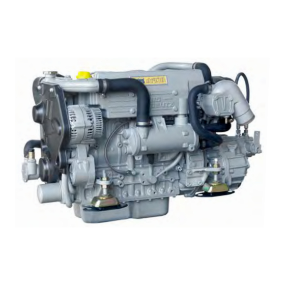
Summary of Contents for Vetus DT4.70
- Page 1 DT4.70 DTA4.85 Operation manual...
- Page 3 Please enter the serial numbers here. These numbers should be quoted when inquiring about Customer Service, Repairs or Spare Parts (see page 6). We reserve the right to make any changes without previous notice. Copyright © 2010 Vetus N.V. Schiedam Holland...
- Page 4 The engine should only be operated, conditions. For the Guarantee Conditions, see the maintained and serviced by persons who Vetus Diesel ‘Service and Warranty are familiar with the former and the haz- Manual’ (320199.05). ards involved.
- Page 5 Recommissioning after Gearbox oil level check Direction of rotation winter storage Draining the after-cooler (charge Identification of engine parts air cooler) DT4.70 Troubleshooting Battery, cables and connections Identification of engine parts Engine oil change DTA4.85 10 Technical data Changing the gearbox oil (Tech-...
- Page 6 1 Safety measures Warning indications Warning indications The following warning indications are used in this manual in the context of safety: Symbols anger aution Indicates that great potential danger exists Indicates that the usage procedures, ac- Indicates that the relevant proce- that can lead to serious injury or death.
- Page 7 1 Safety measures Preventing fire and explosion ire risk • Do not smoke if refuelling. • Do not fill the fuel tank while the engine • Connecting (emergency) extra starting is running! battery • Avoid spilling fuel on hot surfaces. Spilled Only refuel with the engine stopped.
- Page 8 1 Safety measures Prevention of injury • The moving parts of the engine are dan- • Satisfy yourself that everything is in or- • Remove any tool used to bar the engine. gerous. Never touch moving parts of the der before the engine is started again! If you leave this in position, serious injury engine while it is running, to prevent cuts Make sure that no-one is working on or...
- Page 9 1 Safety measures Prevention of injury • Be careful with battery acid! • Make sure that you are wearing suitable If battery acid comes in contact with the clothing before starting work! eyes or skin, rinse the affected part im- For your own safety you will most likely mediately with copious amounts of wa- need special equipment - safety helmet,...
- Page 10 1 Safety measures When problems occur • When the engine stops suddenly: • If the engine overheats: • If the drive belt has broken: If the engine stops suddenly, do not start If the engine should overheat, do not Stop the engine immediately. If an en- it again immediately.
- Page 11 2 Introduction Dear customer, Vetus diesel engines are designed both We have endeavoured to highlight any dif- We are available to help with any additional for pleasure and commercial craft. Con- ferences so that you will able to locate the inquiries.
- Page 12 2 Introduction Data tag Serial number DT470A3452 123456 200910 2500 VD00800 VD00875 VD00880 1 Type plate Position of the type plate 3 Serial number The engine type and the serial number are The type plate is positioned as shown. The serial number is stamped in the engine on the type plate.
- Page 13 2 Introduction Cylinder numbering Direction of rotation VD00881 Cylinder numbering direction of rotation Cylinder numbering Cylinders are numbered consecutively, be- ginning at the flywheel end. Direction of rotation The direction of rotation is viewed towards the flywheel counter clockwise.
- Page 14 2 Introduction Identification of engine parts DT4.70 1 Coolant pump 2 Filler cap (pressure cap) cooling system Cooling system air bleeding nipple 4 Connection water heater ‘IN’ 5 Oil filler cap 6 Lift eye 7 Expansion tank 8 Connection airvent 9 Raw water pump, inlet ø...
- Page 15 2 Introduction Identification of engine parts DT4.70 22 Turbocharger 23 Air filter 24 Lift eye 25 Oil dipstick 26 Extra expansion tank connection (only for keel cooling option) 27 Connection water heater ‘OUT’ 28 Return fuel pipe connection 8 mm...
- Page 16 2 Introduction Identification of engine parts DTA4.85 1 Coolant pump 2 Filler cap (pressure cap) cooling system 3 Cooling system air bleeding nipple 4 Connection water heater ‘IN’ 5 Oil filler cap 6 Lift eye 7 Expansion tank 8 Connection airvent 9 Raw water pump, inlet ø...
- Page 17 2 Introduction Identification of engine parts DTA4.85 24 Zinc anode 25 After cooler 26 Lift eye 27 Oil dipstick 28 Extra expansion tank connection (only for keel cooling option) 29 Connection water heater ‘OUT’ 30 Return fuel pipe connection 8 mm 31 Push-pull throttle cable connection 32 Air inlet 33 Gearbox...
- Page 18 2 Introduction Control panels Engines with intercooling VD00631 Panel, model 34 1 Tachometer/Operating hours counter 8 Indicator light pre-heating 2 Voltmeter 9 Warning light gearbox low oil pressure 3 Starter pre-heat switch/lock 10 Temperature gauge, coolant 4 Warning light high raw water temperature 11 Oil pressure gauge 5 Warning light low oil pressure 6 Warning light high coolant temperature...
- Page 19 2 Introduction Control panels Engines with intercooling VD00576 VD00575 Panel, model 22 Panel, model 10 Panel, without voltmeter, model 21 1 Tachometer/Operating hours counter 8 Indicator light pre-heating 2 Voltmeter 9 Warning light gearbox low oil pressure 3 Starter pre-heat switch/lock 4 Warning light high raw water temperature 5 Warning light low oil pressure 6 Warning light high coolant temperature...
- Page 20 2 Introduction Control panels Engines with keel-cooling VD00630 Panel, model 22 Panel, without voltmeter, model 21 1 Tachometer/Operating hours counter 8 Indicator light pre-heating 2 Voltmeter 9 Warning light gearbox low oil pressure 3 Starter pre-heat switch/lock 4 Warning light second alternator 5 Warning light low oil pressure 6 Warning light high coolant temperature 7 Warning light battery charging...
- Page 21 2 Introduction Operating lever neutral gearbox astern gearbox ahead throttle throttle astern ahead Operating lever for 2 Operating lever for 1 engines engine VD00788 Operating lever Operating lever for 1 or 2 engines. The control lever works as shown in the diagram.
- Page 22 (10.6 UK pt, 12.7 US pt) API: CH-4 / CG-4 / CI-4 ACEA: E3-96 / E4-07 / E5-02 / E7-04 For example: Vetus Marine Diesel Engine Oil 15W40 Shell Rimula R4 L 15W40 VD00809 VD00810 Commissioning the engine 2 Filling with engine oil...
- Page 23 3 First commissioning Vetus engines are normally equipped with Technodrive or ZF-Hurth gearbox- In case your engine is equipped with another brand of gearbox follow the in- structions given in the supplied owner’s manual. VD00867 VD00867 3 Filling gearbox with oil...
- Page 24 3 First commissioning : 8 litres oolant quantity COOLANT (14.1 UK pt, 16.9 US pt) VD00811 VD00812 VD00814 4 Filling the cooling system, i nter Cooling • Remove the filler / pressure cap (1) of • Fill the cooling system. The level of the coolant must be at the low- the filler neck on the top of the heat ex- er edge of the filler neck.
- Page 25 3 First commissioning DO NOT OPEN 1.5 bar VD00844 VD00845 5 Filling the cooling system, k eelCool • Remove the cap (1) of the extra expan- • Fill the cooling system. • Reinstall the plug (2) after the system sion tank. has been bled and the coolant is flowing Use a mixture of 40% antifreeze (ethylene out of the bleeder hole.
- Page 26 3 First commissioning DO NOT OPEN 1.5 bar Use a mixture of 40% antifreeze (ethylene glycol based) and 60% tap water or use a special coolant. For specifications see page 127. aution Never fill the cooling system with sea water or brackish water.
- Page 27 3 First commissioning DO NOT OPEN 1.5 bar Use a mixture of 40% antifreeze (ethylene glycol based) and 60% tap water or use a special coolant. For specifications see page 127. aution Never fill the cooling system with sea water or brackish water.
- Page 28 3 First commissioning DO NOT OPEN 1.5 bar Use a mixture of 40% antifreeze (ethylene glycol based) and 60% tap water or use a special coolant. For specifications see page 127. aution Never fill the cooling system with sea water or brackish water.
- Page 29 3 First commissioning DO NOT OPEN 1.5 bar Use a mixture of 40% antifreeze (ethylene glycol based) and 60% tap water or use a special coolant. For specifications see page 127. aution Never fill the cooling system with sea water or brackish water.
- Page 30 3 First commissioning FUEL Neutral (No throttle, gearbox not engaged) arning Never fill the fuel tank while the engine is running. Do not spill fuel. Prevent un- necessary pollution. VD00789 10 Fuel Other preparations • Fill the fuel tank with diesel fuel. •...
- Page 31 3 First commissioning VD00810 VD00820 12 Test run • Start the engine. • Check the oil level. If necessary top up to • Check that the engine and all connec- the indicated level. tions (fuel, coolant and exhaust) for How to start the engine and what to leaks.
- Page 32 3 First commissioning VD00819 VD00663 VD00791 13 Bleeding 14 Sea trial The cooling system must be bled as soon • Replace the cap on the filler neck. • Check the operation of the remote con- as the engine has reached normal working trol.
- Page 33 4 Running-in In order to ensure a long life for your en- After the first 50 operation hours carry out • Check if all fasteners, bolts and nuts are gine, please observe the following for the the following maintenance: secured, see page 71. first 50 operating hours: •...
- Page 34 5 Use General guidelines General guidelines for use Implementing the following recommenda- • Never run the engine without a thermo- water temperature or battery charging tions will result in longer life and better per- stat. lights up. formance and more economical operation of your engine.
- Page 35 5 Use Starting After repair work: Check that all guards have been replaced First commissioning and that all tools have been removed from Follow the instructions given for ‘First com- the engine. missioning’ on page and further if the When starting with pre-heating, do not use engine is being commissioned for the first any other substance (e.g.
- Page 36 5 Use Starting Neutral Before starting, check the fol- alWays lowing points: (No throttle, gearbox not engaged) • Engine oil level. • Coolant level. • Sea cock open. • Main switch ‘ ’. • Control lever in ‘ ’ position. neutral VD00789 VD00107...
- Page 37 5 Use Starting Ambient Pre-heating Temperature time Below 0°C(+32°F) 15 seconds 0°C to 10°C 10 seconds (+32°F to +50°F) 10°C to 30°C 5 seconds (+50°F to +86°F) Above 30°C (86°F) VD00107 3 Pre-heating The ideal pre-heating time depends on Turn the key further clockwise to the ‘ ’...
- Page 38 5 Use Starting VD00109 VD00110 4 Starting aution Now turn the key further to the ‘start’ posi- Release the key as soon as the engine fires Release the key if the engine does not fire tion. (the key will return to the ‘on’ position) and within 10 seconds.
- Page 39 5 Use Starting VD00629 aution Check that the indicator lights for oil pres- Let the engine run for 5 to 10 minutes in Never turn the key to the ‘ ’ position start sure and alternator are off. neutral. A good warm up is essential to en- while the engine is running.
- Page 40 16). This can lead to carbon deposits in the Also the number of running hours is indi- combustion chambers and incomplete cated. combustion of fuel. Idling speed : - DT4.70: 900 rpm - DTA4.85: 900 rpm...
- Page 41 5 Use Cruising VD00578 VD00663 VD00664 Voltmeter Temperature gauge Oil pressure gauge Indicating the battery voltage. Indicating the temperature of the internal With the engine at operating temperature, When the engine is running, the battery cooling system. the oil pressure is: voltage should be between 12 and 14 The operating temperature is 82˚C - 97˚C.
- Page 42 5 Use Cruising 9 Warning lights 10 Alarm buzzer None of the five warning lights should light Oil pressure, battery charging and tem- up while the engine is running. perature indicator lights are all connected to an alarm buzzer. If this alarm buzzer sounds while running, Stop the engine im- mediately!
- Page 43 5 Use Stopping VD00790 VD00106 VD00105 11 Stopping Reduce engine speed to idle and place the Turn the key to the left to the ‘o ’ posi- Note The ‘s ’ position, left of the ‘o ’ control lever in ‘n ’...
- Page 44 6 Maintenance Introduction Introduction The following guidelines should be ob- Failure to carry out maintenance can result served for daily and periodic maintenance. in faults and permanent damage to the en- Perform each function at the indicated time gine. interval. No claim can be made on the Guarantee if The intervals stated are for normal opera- maintenance has been neglected.
- Page 45 6 Maintenance Introduction Keep record of the following information in • Oil pressure and coolant temperature. the logbook and/or the ‘Service and Guar- antee Book’: • Parts on which maintenance is conduct- ed and type of maintenance (adjustment, • Total engine hours (reading engine hour repair or replacement), and the results of counter).
- Page 46 6 Maintenance Maintenance schedule Every 10 hours or daily, before starting page Every 100 hours, at least once every year page Check engine oil level Drain water from fuel filter Check coolant level Check gearbox oil level Check water strainer Drain charge air cooler Battery, cables and cable connections After the first 50 hours...
- Page 47 Check starter motor 79 Check alternator 79 Check turbocharger Every 3000 hours page Check and adjust injector pressure evaar Consult the service manual, work to be carried out by a Vetus Stop the engine before carrying out any maintenance work. dealer.
- Page 48 6 Maintenance Checking engine oil level Daily, before starting. VD00810 VD00126 VD00809 1 Check oil level 2 Oil level 3 Topping up oil Turn the engine off. The oil level must be at or near the upper The oil filling cap is on top of the valve The dipstick is located on the starboard mark on the dipstick .
- Page 49 6 Maintenance Checking coolant level Daily, before starting. VD00831 VD00821 VD00822 Checking coolant level 5 Coolant level Topping up coolant Check the coolant level in the filler neck. The level of the coolant must be at the low- Top up if necessary. This has to be checked when the engine er edge of the filler neck.
- Page 50 6 Maintenance Checking and cleaning the raw water strainer Daily, before starting. VD00801 VD00802 Checking the raw water strainer Cleaning the strainer Check daily whether there is any dirt in the Close the sea cock before removing the lid Check the sealing between the lid and raw water strainer.
- Page 51 6 Maintenance Draining of water from the water separator/fuel filter Every 100 operating hours. VD00815 VD00803 9 Drain fuel filter 10 Empty water separator anger Do not smoke when draining off water and • Open the drain plug at the lower side of Empty the separately installed water sepa- sediment.
- Page 52 6 Maintenance Draining of water from the water separator/fuel filter Every 100 operating hours. VD00107 VD00823 11 Bleeding After the water separator/fuel filter has • Turn the key of the starter switch to posi- • Open the bleeding nipple at the filter to been drained, the air has to be bled from tion ‘ON’...
- Page 53 6 Maintenance Draining of water from the water separator/fuel filter Every 100 operating hours. VD00109 12 Start the engine • Operate the starter switch until the en- gine fires; release the starter switch if the engine does not fire within 6 seconds. •...
- Page 54 Gearbox oil level check Every 100 operating hours. VD00870 VD00870 13 Oil level check Vetus engines are normally equipped with • Take the dipstick out of the gearbox The oil level must between the two marks Technodrive or ZF-Hurth gearboxes. Con- housing by pulling or unscrewing.
- Page 55 6 Maintenance Draining the after-cooler (charge air cooler) Every 100 operating hours. VD00899 Draining after-cooler Condensate accumulating in the after • Remove the drain plug from the after cooler must be drained every 100 hours of cooler and check whether all the con- at least once a year.
- Page 56 6 Maintenance Battery, cables and connections Every 100 operating hours. Warning notes and safety regulations Corrosive hazard: Warning note: for working with batteries • Battery acid is highly corrosive, • Do not place batteries in direct therefore: daylight without protection. Wear eye protection.
- Page 57 6 Maintenance Battery, cables and connections Every 100 operating hours. VD00117 Battery, battery connections Keep battery clean and dry. Ensure that clamps make good contact af- ter reassembling. • Remove battery cables (negative first). • Hand tighten the bolts only. •...
- Page 58 VD00118 VD00121 VD00122 VD00123 Checking specific gravity Hydrometer operation Every Vetus Maintenance-free battery has • Green dot visible - State of charge 65 % n case of low level, caused by over-charg- a hydrometer (1) built into the cover. Visual or more.
- Page 59 6 Maintenance Battery, cables and connections Every 100 operating hours. Conventional batteries Conventional batteries Specific State of gravity charge 1.280 100% 1.200 recharge recharge 1.120 immediately VD00119 VD00120 Checking electrolyte level Checking specific gravity For conventional batteries it is required to Measure the electrolyte specific gravity of The temperature of the electrolyte dur- check the electrolyte level regularly.
- Page 60 6 Maintenance Engine oil change Every 500 operating hours. Engine oil change Change the engine oil every 500 hours of Change the oil with a switched off engine arning operation (together with engine oil filter re- at operation temperature. (Lube oil tem- placement).
- Page 61 6 Maintenance Engine oil change Every 500 operating hours. VD00817 VD00897 VD00818 Drain oil 22 Removing the oil filter • Remove the dipstick; insert the suction • After draining remove the suction hose • Unscrew the oil filter, with a commercially hose of the supplied sump pump into of the sump pump out of the dipstick available tool, when all the oil has been...
- Page 62 6 Maintenance Engine oil change Every 500 operating hours. 6.3 litres : 08-00085 apaCity il filter Code ) (11 UK pt, 13.3 US pt) ilter VD00124 VD00824 VD00809 Oiling the oil seal Oil filter installation Refilling with oil • Clean the contact surface of the gasket. •...
- Page 63 6 Maintenance Changing the gearbox oil (Technodrive) Every 500 operating hours. VD00871 VD00867 Draining the oil Filling with new oil • Remove the drain plug to drain the oil. • Refill the gearbox to the correct level via In case your engine is equipped with an- the filling hole.
- Page 64 6 Maintenance Changing the gearbox oil (ZF-Hurth) Every 500 operating hours. VD00872 VD00871 VD00644 Draining the oil Changing the oil filter Drain the oil with the aid of a separate Or, if sufficient space below the gearbox is The filter element must be replaced at the sump pump.
- Page 65 6 Maintenance Changing the gearbox oil (ZF-Hurth) Every 500 operating hours. : CT50081 ilter element Code VD00645 VD00867 Filling with new oil • Withdraw the filter element (1). • Refill the gearbox to the correct level via In case your engine is equipped with an- the dipstick opening.
- Page 66 6 Maintenance Fuel filter replacement Every 500 operating hours. VD00825 Fuel filter removal The fuel filter is to be replaced as a unit. anger Keep naked flames away when working on • Close the fuel stopcock. the fuel system. Do not smoke! •...
- Page 67 6 Maintenance Fuel filter replacement Every 500 operating hours. : STM3690 uel filter Code VD00154 VD00830 Fuel filter installation • Clean any debris from the filter carrier • Fill the new filter with clean diesel fuel. • Open fuel stopcock. rim.
- Page 68 6 Maintenance Cleaning filter fuel lift pump Every 500 operating hours. : STM4050 uel filter Code Fuel filter STM7220 Fuel lift pump • Check, and if necessary clean, filter in- • Open the fuel stop cock. side the fuel lift pump. •...
- Page 69 6 Maintenance Bleeding, after fuel filter replacement Every 500 operating hours. VD00107 VD00109 34 Bleeding Start the engine After replacing the fuel filter and cleaning • Start the engine • Check for leaks once more. the pilot filter inside the fuel lift pump the air has to be bled from the fuel system.
- Page 70 6 Maintenance Checking the V-belt Every 500 operating hours. : 08-00083 belt Code VD00826 VD00834 VD00034 Remove the protection cover Inspection V-belt • Loosen the 4 fixing bolts. • Remove the protection cover. • Inspect the belt for wear and tear (fraying and cracking).
- Page 71 6 Maintenance Checking the V-belt Every 500 operating hours. 10 kgf 20 lbf max. 12 mm 1/2” VD00833 VD00835 VD00826 Checking tension 39 Tensioning V-belt Reinstall the protection cover • Check tension of the V-belt by applying • Loosen the bolt of the adjustment brack- •...
- Page 72 6 Maintenance Flexible engine mounts Every 500 operating hours. 41 Check flexible engine mounts • Check the bolts which secure the damp- • Inspect the rubber element of the en- er element, the mounting bolts to engine gine support for cracks. Also check the bed and the nuts at the adjustment spin- deflection of the damper element, the dle for tightness.
- Page 73 6 Maintenance Hose connections and fasteners Every 500 operating hours. VD00820 Inspection hose connections Check fasteners • Inspect all hose connections of the cool- • Check tightness of all fasteners, bolts ing system. (Cracked hoses, loose hose and nuts. clamps).
- Page 74 6 Maintenance Raw water pump inspection Every 1000 operating hours. Only engines with intercooling! 1,2 x 6,5 VD00836 VD00837 Raw water pump inspection Pump cover removal Impeller removal The rubber impeller of the raw water pump Inspection where appropriate changing is •...
- Page 75 6 Maintenance Raw water pump inspection Every 1000 operating hours. + o-r : STM8074 : 08-00360 mpeller Code Code VD00127 VD00004 47 Impeller inspection Re-install the impeller Replacing the pump cover • Inspect the impeller for damage. • The impeller should be lubricated with •...
- Page 76 6 Maintenance Coolant replacement Every 1000 operating hours. 50 Coolant replacement anger arning The coolant has to be replaced every 1000 Be aware of the risk of skin burning dur- Cooling system protec- operating hours or at least once every two ing draining the hot coolant! Used coolant tive liquids must be dis- years.
- Page 77 6 Maintenance Coolant replacement Every 1000 operating hours. 1,2 x 6,5 VD00882 VD00873 VD00873 51 Drain coolant • Remove the plug (1) and the filler cap (2) • Remove the hose to the oil cooler (3). • Remove the drain plugs (4) and (5) to allow air into the cooling system.
- Page 78 6 Maintenance Coolant replacement Every 1000 operating hours. 8 litres oolant quantity (14.1 UK pt, 16.9 US pt) VD00812 VD00814 52 Fill cooling system • Fill the cooling system. The level of the coolant must be at the low- er edge of the filler neck. When keel cooled, see page 23.
- Page 79 6 Maintenance Coolant replacement Every 1000 operating hours. VD00831 VD00822 • Check the coolant level after the engine • Remove the filler cap has been run again for the first time, has reached operating temperature and then • Top up if necessary. has cooled back to ambient tempera- ture.
- Page 80 6 Maintenance Changing the air filter Every 1000 operating hours. : 08-00084 ir filter Code 1,2 x 6,5 VD00859 VD00860 Changing the air filter • Stop the engine. Remove the old filter and fit a new filter arning (3). Never clean the filter element with petrol or •...
- Page 81 If the Bendix does not engage nator can be turned easily. If this is not properly, contact your Vetus dealer. the case, contact your Vetus dealer.
- Page 82 6 Maintenance Cleaning the heat exchanger Cleaning of the heat exchanger is not a Under normal conditions of use cleaning Possible causes of fouling are: routine maintenance job. the heat exchanger is not necessary! Small rubber particles from a damaged raw water pump impeller.
- Page 83 6 Maintenance Cleaning the heat exchanger VD00839 VD00819 Drain the coolant • To do this, remove the drain plug from • Remove the filler cap on the top of the the heat exchanger housing. expansion tank to allow air into the cool- ing system and check that all the liquid drains out.
- Page 84 6 Maintenance Cleaning the heat exchanger 1,2 x 6,5 1,2 x 6,5 VD00840 VD00841 Removing the raw water hoses Removing the exhaust hose • Close the sea cock. • Remove the exhaust hose from the ex- haust injection bend. • Remove both the raw water hoses.
- Page 85 6 Maintenance Cleaning the heat exchanger VD00843 VD00842 VD00847 Removing the end covers Take out the heat exchanger • Unscrew the 2 cap nuts and pull the rod • Slide the heat exchanger out of the out of the end covers. housing.
- Page 86 6 Maintenance Cleaning the heat exchanger VD00746 VD00863 VD00864 Cleaning the heat exchanger • Clean the heat exchanger: Use a pipe • Ensure that both heat exchanger end • Clean the contact surfaces of the O- cleaner to remove fouling in the pipes. chambers are free from dirt.
- Page 87 6 Maintenance Cleaning the heat exchanger : 08-00061 (2 x) ings Code : STM2018 (2 x) opper washers Code VD00866 VD00865 Replacing heat exchanger Fitting end covers • Replace the heat exchanger in the origi- • Fit the end covers in the housing. •...
- Page 88 6 Maintenance Cleaning the after cooler aution Cleaning of the after cooler is not a rou- Possible causes of fouling of the tubes of The heat exchanger element in the after tine maintenance job. the after cooler are: cooler is very vulnerable! Small rubber particles from a damaged If the performance of the engine decreas- raw water pump impeller.
- Page 89 6 Maintenance Cleaning the after cooler VD00901 VD00902 VD00903 Removing the raw water hoses Take out the heat exchanger • Close the sea cock. • Unscrew the 2 cap nuts. Slide the heat exchanger out of the hous- ing. • Remove both the raw water hoses.
- Page 90 6 Maintenance Cleaning the after cooler VD00898 VD00905 VD000906 Cleaning the heat exchanger • Clean the tube of the heat exchanger; • Ensure that both heat exchanger end • Clean the contact surfaces of the O- use a pipe brush and fresh water to re- chambers are free from dirt.
- Page 91 6 Maintenance Cleaning the after cooler : 08-00061 (2 x) ings Code : STM2018 (2 x) opper washers Code VD00905 VD00907 Replacing the heat exchanger Fitting end covers • Put the heat exchanger back in exactly • Fit the end covers in the housing. •...
- Page 92 Good ventilation prevents damp in the en- gine compartment, thus preventing corro- Consult a Vetus Dealer if help is required sion of the engine from occurring. with this. Inspections and maintenance work to be...
- Page 93 7 Winter storage procedure Inspections and maintenance work to be carried out: page Clean the engine, remove any salt. Paint any rust spots and spray the whole engine with a protective medium, for example CRC protective 6-66. Check the zinc anodes. Drain off the water from the fuel system and fill the fuel tank.
- Page 94 7 Winter storage procedure 13 ( ”) VD00827 VD00861 1 Corrosion protection 2 Zinc anode The various parts of the engine (except the There is a zinc anode in the heat exchang- • Check the zinc anodes; a new zinc an- engine block) have been treated with an er to protect engine parts that come into ode is 13 mm (...
- Page 95 7 Winter storage procedure : 08-00034 inC anode Code : STM9315 eal washer Code VD00828 VD00829 Check and replace the zinc anodes as fol- • Replace the (new) zinc anode and the lows: copper ring. Use a sealant, for example Loctite®...
- Page 96 7 Winter storage procedure VD00803 VD00830 3 Fuel system • Drain the water from the water separator/ • Fit a new fuel filter element. (page fuel filter and the fuel tank. Make sure that the tank is completely filled with fuel. This to prevent the forming of condensation...
- Page 97 ** Only use DIN EN 590 Diesel fuel. utes at idling speed. E.g.: Preferably water-free fuel. Vetus Marine Diesel Engine Oil 15 W-40 Collect some fuel from the return pipe, Shell Nautilus Premium Inboard 15 while engine is running. W-40...
- Page 98 7 Winter storage procedure Heat exchanger Only clean the heat exchanger if this is absolutely necessary, see page Combine flushing the raw water cir- cuit with fresh water with running the Raw water pump engine with the protective fuel mix- Check the impeller of the raw water ture, see Protective fuel mixture pump at least once every two years,...
- Page 99 7 Winter storage procedure VD00831 6 Fresh water cooling system Take care that no anti-freeze is spilled into To avoid corrosion during winter storage N.B. Replacing the coolant is only neces- the waterway (anti-freeze is poisonous). the cooling system must be filled with an sary if the coolant present in the cooling antifreeze/water mixture (or a coolant).
- Page 100 7 Winter storage procedure VD00817 VD00832 VD00867 7 Lubrication system 8 Gearbox oil change With the engine still at operating tempera- • Replace the oil filter and change the en- • Stop the engine and change the oil of ture: (If not, run the engine until warm, then gine oil, see page 58;...
- Page 101 7 Winter storage procedure VD00139 CT40063 9 Electrical system • Disconnect the battery cables. • Charge batteries during winter lay-up • Follow the recommendations given on regularly if required! pages or consult the recom- mendations given by the battery sup- plier for inspection and maintenance of the batteries.
- Page 102 Drain the water from the fuel system. Check the raw water system. Consult a Vetus Dealer if help is required with this. Check the coolant level in the internal cooling system. Inspections and maintenance work to be Check the oil level.
- Page 103 8 Recommissioning after winter storage VD00803 VD00141 VD00137 1 Fuel system • Drain the water from the water separator/ • Drain the water from the fuel tank. • Open the fuel valve. fuel filter. (page 49)
- Page 104 8 Recommissioning after winter storage VD00874 VD00125 VD00874 2 Raw water cooling system • Check that the lid of the raw water strain- • Check that the lid of the raw water pump • Re-tighten possible loose hose clamps. er is reinstalled. is in place (page 72, 73).
- Page 105 8 Recommissioning after winter storage VD00138 VD00831 VD00810 3 Fresh water cooling system 4 Lubrication system • Open the sea cock. • Check the coolant level. (page • Check the engine oil level. (page...
- Page 106 8 Recommissioning after winter storage CT40063 VD00140 VD00107 5 Electrical system Switching on • Make sure that the batteries are fully • Connect the batteries. • Turn the starter key on the instrument charged. (page 54, 99). panel to ‘ON’; the indicator lights for oil pressure and the dynamo will now come on and the alarm buzzer will sound.
- Page 107 8 Recommissioning after winter storage VD00820 VD00581 Check engine for leaks Checking instruments and remote controls • Start the engine. • Check the operation of the instruments, the remote control and the gearbox. • Check the fuel system, the cooling sys- tem and the exhaust for leakage.
- Page 108 9 Troubleshooting General Engine faults are in most cases caused by If you are unable to identify the cause of anger improper operation or insufficient mainte- the fault or to rectify it yourself, then con- Before starting, make sure that nobody is in nance.
-
Page 109: Table Of Contents
9 Troubleshooting Fault finding table Fault page Engine will not crank Engine cranks but will not start, no smoke from exhaust Engine cranks but will not start, smoke from exhaust Engine starts but runs unevenly (rough idling) or stalls Engine does not reach maximum RPM under load Engine overheats Engine not firing on all cylinders Engine has little or no oil pressure... -
Page 110: Engine Will Not Crank
9 Troubleshooting Fault finding table 2 Engine cranks but will not start, no smoke from exhaust 1 Engine will not crank Possible fault Remedy Possible fault Remedy Faulty or discharged battery Check / recharge battery and (Nearly) Empty fuel tank. Refill. -
Page 111: Engine Cranks But Will Not Start, Smoke From Exhaust
9 Troubleshooting Fault finding table 4 Engine starts but runs unevenly (rough idling) or 3 Engine cranks but will not start, smoke from exhaust stalls Possible fault Remedy Possible fault Remedy Faulty injector/injection pump. Check, replace if required. (Nearly) Empty fuel tank. Refill. -
Page 112: Engine Does Not Reach Maximum Rpm Under Load
9 Troubleshooting Fault finding table 5 Engine does not reach maximum rpm under load 5 Engine does not reach maximum rpm under load Possible fault Remedy Possible fault Remedy Fuel pre filter clogged . Clean/replace. Turbocharger damaged . Replace. Fuel filter clogged with water Check or replace. -
Page 113: Engine Overheats
9 Troubleshooting Fault finding table 6 Engine overheats 6 Engine overheats Possible fault Remedy Possible fault Remedy Faulty injector/injection pump. Check, replace if required. Motor becomes apparently Check / replace. overheated as a result of faulty Sea cock closed. Open. temperature switch, sensor or Raw water strainer clogged. -
Page 114: Engine Not Firing On All Cylinders
9 Troubleshooting Fault finding table 7 Engine not firing on all cylinders 8 Engine has little or no oil pressure Possible fault Remedy Possible fault Remedy Fuel supply line restricted. Check / clean. Oil level too low. Increase level. Fuel filter clogged with water Check or replace. -
Page 115: Engine Oil Consumption Excessive
9 Troubleshooting Fault finding table 9 Engine oil consumption excessive 10 Fuel consumption excessive Possible fault Remedy Possible fault Remedy Oil level too high. Lower level. Faulty injector/injector pump. Check, replace if necessary. Incorrect lube oil SAE class or Replace. Incorrect fuel quality or dirty Check fuel. -
Page 116: Black Exhaust Smoke (Idling)
9 Troubleshooting Fault finding table 11 Black exhaust smoke (idling) 13 Black exhaust smoke (at load) Possible fault Remedy Possible fault Remedy Injector fault Check /replace. Faulty injector / injection Check / replace if required. pump. Oil level too high. Lower level. -
Page 117: White Exhaust Smoke (At Full Load)
9 Troubleshooting Fault finding table 14 White exhaust smoke (at full load) 15 Burnt oil trace in exhaust line . Possible fault Remedy Possible fault Remedy Faulty injector/injection pump. Check, replace if required. Oil level too high . Lower level. Air in fuel system. - Page 118 10 Technical data Engine specifications Model DT4.70 DTA4.85 General Make Vetus Deutz Number of cylinders Based on TD 2009 L04 Type 4-stroke diesel, in-line Injection Direct injection Aspiration Turbo-charged Turbo-charged, after-cooled Bore 90 mm Stroke 90 mm Total displacement 2290 cm (140 cu.inch)
- Page 119 10 Technical data Engine specifications Model DT4.70 DTA4.85 Maximum Output at the flywheel (ISO 3046-1) 50 kW (69 hp) 63 kW (85 hp) at the prop shaft (ISO 3046-1) 49 kW (68 hp) 62 kW (84 hp) at no. of revolutions of...
- Page 120 10 Technical data Engine specifications Model DT4.70 DTA4.85 Oil lubrication system Oil capacity, max. without oil filter 6.0 litres (10.6 UK pt, 12.7 US pt) with oil filter 6.3 litres (11.1 UK pt, 13.3 US pt) Oil Filter 08-00085 Oil temperature in sump max.
- Page 121 10 Technical data Engine specifications Model DT4.70 DTA4.85 Combustion air Air filter 08-00084 Intake vacuum pressure max. 25 mbar (0.74 in Hg) Turbo pressure at max. load max. 760 mbar (22.4 in Hg) Exhaust system Exhaust diameter 75 mm (3”) Exhaust back pressure at specified output max.
- Page 122 10 Technical data Gearbox specifications Model DT4.70 DTA4.85 Gearbox Gear ratio Gear ratio Technodrive: type TM345 (1.54) 2.00 2.47 (1.54) 2.00 2.47 type TM345A (1.54) 2.00 2.47 (1.54) 2.00 2.47 type ZF25 1.969 2.800 1.969 2.800 (1.548) 1.926 2.292 (2.480) (1.548)
- Page 123 10 Technical data Torque wrench settings Screw connection Size Class Torque Remark Engine bracket front 41 Nm Engine bracket rear 42 Nm 35 Nm + Cylinder head bolts - Engine block 10.9 Use new bolts. Observe tightening sequence. 60° + 60° Rocker - Cylinder head 27 Nm Rocker cover...
- Page 124 10 Technical data Torque wrench settings Screw connection Size Class Torque Remark Fuel line - Injection pump 1/2" 9 Nm Oil filter - Oil cooler Hand tight Lubricate the oil seal. Oil cooler - Adaptor 41 Nm Oil pressure switch M10x1 20 Nm Coolant pump - Timing cover...
- Page 125 11 Operating media Fuel Fuel Quality Grade Winter-grade fuel Use commercially available diesel fuel with less than 0.5% sulphur Waxing may occur at low temperatures, clogging the fuel system content. Don’t use fuel with more than 1 % sulphur! and reducing engine efficiency. If the ambient temperature is less than O°C (+32°F), winter-grade The following fuel specifications / standards are approved: fuel -suitable down to -15°C (+5°F) - should be used.
- Page 126 This can in turn lead to higher For example: frictional resistance and more effort, which forms a hindrance to Vetus Marine Diesel Engine Oil 15W40 reaching the starting rpm required for a dependable start, and this Shell Rimula R4 L 15W40 results in a reduced life-span.
- Page 127 11 Operating media Lubricating oil Limits concerning motor oil aution If an analysis of the used lubricating oil is Do not mix oil of different brands together. How often the oil has to be changed de- conducted to determine its condition, con- Oils of different brands are mostly not com- pends on the characteristics of the fuel.
-
Page 128: Technodrive: Type Tm345
Without oil cooler, content oil cooler approx. 0.3 litres (0.53 UK pt, 0.63 US pt) : Automatic Transmission Fluid; Transmission oil type A, Suffix A. For example: Vetus Transmission Oil Shell Donax T6 Gulf Synth Other brands of gearboxes: See supplied owner’s manual for oil type and quantities. - Page 129 11 Operating media Coolant Coolant fluid Water quality for coolant preparation The preparation and monitoring of coolant in inter-cooled engines Use preferably tap water. is especially important because corrosion, cavitation and freezing can lead to engine damage. Use as coolant a mixture of a cooling If available fresh water is used;...
- Page 130 12 Wiring diagrams Engine with panel model ‘34’ Key switch Engine panel model '34' Yellow White Violet Orange Black Plug 'A' Socket 'A' Fuse Pre- Stop relay heating relay Auxiliary Battery start relay main switch ϑ Battery Stop Injection Pre-heating Starter motor solenoid Fuel lift pump...
- Page 131 12 Wiring diagrams Engine with panel model ‘34’ Tachometer/ Oil pressure Temperature Voltmeter hour counter gauge gauge ϑ 17/19 Warning lights Gearbox oil press. − 19/94 (31) (15) Plug 'B' Plug 'C' Socket 'B' Socket 'C' Transparent Brown/ Blue/ Yellow/ Yellow/ Green Brown...
- Page 132 12 Wiring diagrams Engine with panel model ‘22’ Key switch Engine panel model '22' Yellow White Violet Orange Black Plug 'A' Socket 'A' Fuse Pre- Stop relay heating relay Auxiliary Battery start relay main switch ϑ Battery Stop Injection Pre-heating Starter motor solenoid Fuel lift pump...
- Page 133 12 Wiring diagrams Engine with panel model ‘22’ Tachometer/ Voltmeter hour counter 17/19 Warning lights Gearbox oil press. − 19/94 (31) (15) Plug 'B' Socket 'B' Socket 'C' Transparent Yellow/ Brown/ Blue/ Yellow/ Green Brown Blue Gray Green Black Green ϑ...
- Page 134 13 Overall dimensions 883 (34 ”) DT4.70 TM345A 8° 231 (9 ”) 490 (19 ”) 230 (9 ”) 989 (38 ”) DT4.70...
- Page 135 13 Overall dimensions 1 Exhaust ø 75 mm 2 Fuel supply ø 8 mm 3 Fuel return ø 8 mm 4 Raw water intake ø 28 mm 465 (18 ”) 554 (21 ”) 1 : 10...
-
Page 136: Dta4.85
13 Overall dimensions 883 (34 ”) DTA4.85 TM345A 8° 231 (9 ”) 490 (19 ”) 230 (9 ”) 989 (38 ”) DTA4.85... - Page 137 13 Overall dimensions 1 Exhaust ø 75 mm 2 Fuel supply ø 8 mm 3 Fuel return ø 8 mm 4 Raw water intake ø 28 mm 465 (18 ”) 554 (21 ”) 1 : 10...
- Page 138 14 Index Control panels Coolant After cooler Electrical system 99, 104 Drain After cooler, Cleaning Electrical system, Counter plug 13, 15 Level Air bleeding nipple 12, 14 Electrolyte level Pump 12, 14 Air filter 13, 14 Engine mounts, Flexible 12, 14, 70 Quantity Air inlet 13, 15...
- Page 139 14 Index Fresh water cooling system 97, 103 Overall dimensions Fuel 28, 123 Heat exchanger 12, 14 Fuel filter Heat exchanger, Cleaning Fuel filter replacement Pre-heating Hose connections Fuel lift pump 13, 15 Pre-heating, Indicator light 16, 17, 18 Fuel lift pump, Cleaning filter Prop shaft lubrication, Connection for Fuel supply pipe 13, 15...
- Page 140 14 Index Sea trial Serial number Warning indications Serial numbers Warning lights Starter motor 13, 15, 79 Battery charging 16, 17, 18 Starting Gearbox low oil pressure 16, 17, 18 Start the engine High coolant temperature 16, 17, 18 Stopping High raw water temperature 16, 17 Stop relay...
- Page 143 Service- og garantibog / Service- och garantihäfte Dansk / Svenska / Service- og garantibok / Huolto- ja takuukirja Norsk / Suomeksi) 361531.01 Onderdelenboek / Parts manual DT4.70, DTA4.85 (Nederlands / English) 362433.01 Service manual DT4.70, DTA4.85 (English / Deutsch / Français / Español)
- Page 144 F O K K E R S T R A A T 5 7 - 3 1 2 5 B D S C H I E D A M - H O L L A N D - T E L . : + 3 1 ( 1 0 ) 4 3 7 7 7 0 0 n. v. FAX:+31 (10) 4372673 - 4621286 - E-MAIL: sales@vetus.nl - INTERNET: http://www.vetus.com 360502.01 2010-11...
Need help?
Do you have a question about the DT4.70 and is the answer not in the manual?
Questions and answers