Perkins 1106C Genset Systems Operation Testing And Adjusting
Hide thumbs
Also See for 1106C Genset:
- Operation and maintenance manual (92 pages) ,
- Troubleshooting manual (188 pages)

Related Manuals for Perkins 1106C Genset


Summary of Contents for Perkins 1106C Genset
- Page 1 KENR6931 May 2007 Systems Operation Testing and Adjusting 1106C Genset PK (Engine)
- Page 2 These changes can affect the service that is given to the product. Obtain the complete and most current information before you start any job. Perkins dealers or Perkins distributors have the most current information available. When replacement parts are required for this product Perkins recommends using Perkins replacement parts.
-
Page 3: Table Of Contents
KENR6931 Table of Contents Table of Contents Gear Group - Inspect ..........75 Vibration Damper - Check ........75 Electrical System Systems Operation Section Alternator - Test ............ 77 Battery - Test ............78 General Information Charging System - Test ........78 Introduction ............ -
Page 4: Introduction
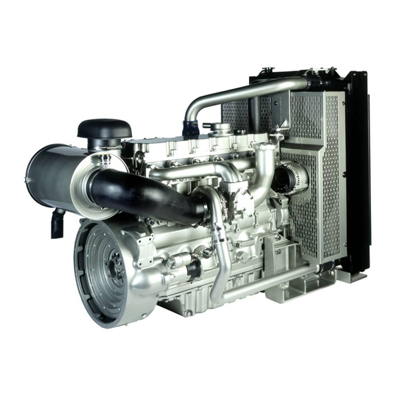
KENR6931 Systems Operation Section Systems Operation Section General Information i02756359 Introduction The following model views show a typical 1106C Genset. Due to individual applications, your engine may appear different from the illustrations. g01329939 Illustration 1 Front left engine view (1) Fuel manifold (Rail) (6) Hand primer (11) Water pump (2) Canister for the crankcase breather... - Page 5 (20) Alternator (25) Starting motor (30) Rear lifting eye The 1106C genset is electronically controlled. The The pistons have two compression rings and an oil 1106C genset uses an Electronic Control Module control ring. The groove for the top ring has a hard (ECM) that receives signals from the fuel injection metal insert in order to reduce wear of the groove.
-
Page 6: Engine Operation
KENR6931 Systems Operation Section The crankshaft has seven main bearing journals. End The fuel injection pump (1) that is installed on the play is controlled by thrust washers which are located left side of the engine is gear-driven from the timing on both sides of the number six main bearing. - Page 7 The engine has a cast iron cylinder head. The inlet manifold is integral within the cylinder head. There The cast iron cylinder block for the 1106C genset are two inlet valves and two exhaust valve for each has six cylinders which are arranged in-line. The cylinder.
- Page 8 KENR6931 Systems Operation Section Pistons, Rings and Connecting Crankshaft rods g01196830 Illustration 7 g01205645 Illustration 6 The crankshaft is a chromium molybdenum forging. The crankshaft has seven main journals. Thrust The pistons have a Quiescent combustion chamber washers are installed on both sides of number six in the top of the piston in order to provide an efficient main bearing in order to control the end play of the mix of fuel and air.
- Page 9 KENR6931 Systems Operation Section Gears and Timing Gear Case g01194949 Illustration 10 The crankshaft oil seal is mounted in the aluminum timing case. The timing case cover is made from pressed steel. g01205646 Illustration 8 The timing gears are made of steel. Vibration Damper The crankshaft gear drives an upper idler gear and a lower idler gear.
-
Page 10: Air Inlet And Exhaust System
KENR6931 Systems Operation Section i02656284 Air Inlet and Exhaust System g01205681 Illustration 11 Air inlet and exhaust system (1) Exhaust manifold (5) Aftercooler core (9) Air inlet from the air cleaner (2) Electronic unit injector (6) Exhaust outlet (10) Inlet valve (3) Glow plug (7) Turbine side of turbocharger (11) Exhaust valve... - Page 11 KENR6931 Systems Operation Section Turbocharger • Compression • Power • Exhaust On the compression stroke, the piston moves back up the cylinder and the inlet valves (10) close. The cool compressed air is compressed further. This additional compression generates more heat. Note: If the cold starting system is operating, the glow plugs (3) will also heat the air in the cylinder.
- Page 12 KENR6931 Systems Operation Section A wastegate is installed on the turbine housing of the turbocharger. The wastegate is a valve that allows exhaust gas to bypass the turbine wheel of the turbocharger. The operation of the wastegate is dependent on the pressurized air (boost pressure) from the turbocharger compressor.
-
Page 13: Cooling System
KENR6931 Systems Operation Section Valve System Components i02404368 Cooling System Introduction (Cooling System) The cooling system has the following components: • Radiator • Water pump • Cylinder block • Oil cooler • Cylinder head • Water temperature regulator (thermostat) g01334457 Illustration 15 Valve system components (1) Bridge... -
Page 14: Lubrication System
KENR6931 Systems Operation Section Coolant Flow g01206083 Illustration 16 Coolant flow (1) Radiator (5) Cylinder head (7) Bypass for the water temperature (2) Water pump (6) Water temperature regulator (thermostat) regulator (thermostat) (3) Cylinder block and housing (4) Engine oil cooler The coolant flows from the bottom of the radiator (1) i02413834 to the centrifugal water pump (2). -
Page 15: Electrical System
KENR6931 Systems Operation Section Piston cooling jets are installed in the engine. The The engine oil pump has an inner rotor with four piston cooling jets are supplied with the oil from the lobes. The inner rotor is mounted to a shaft which also carries the drive gear. -
Page 16: Cleanliness Of Fuel System Components
KENR6931 Systems Operation Section • Rectified The alternator is an electro-mechanical component. The alternator is driven by a belt from the crankshaft pulley. The alternator charges the storage battery during the engine operation. The alternator is cooled by an external fan which is mounted behind the pulley. - Page 17 The sealing plugs must not be reused. Dispose of the sealing plugs immediately after use. Contact your nearest Perkins dealer or your nearest approved Perkins distributor in order to obtain the correct sealing plugs. New Components High pressure lines are not reusable.
-
Page 18: Fuel Injection
KENR6931 Systems Operation Section i02709987 Fuel Injection Introduction (Fuel Injection) g01202269 Illustration 19 Diagram of the basic fuel system (typical example) (1) Electronic unit injector (6) Crankshaft position sensor (11) Coolant temperature sensor (2) Solenoid for the fuel injection pump (7) Boost pressure sensor (12) Diagnostic connector (3) Wastegate solenoid (if equipped) - Page 19 KENR6931 Systems Operation Section Low Pressure Fuel System g01360010 Illustration 20 Low pressure fuel system (typical example) (1) Primary fuel filter (7) Fuel injection pump (D) Return from the electronic unit injectors (2) Water separator (A) Outlet for high pressure fuel to the fuel (E) The fuel inlet from the fuel tank (3) Fuel transfer pump manifold (rail)
- Page 20 KENR6931 Systems Operation Section Fuel is drawn from the fuel tank (E) through a 20 micron Primary fuel filter (1) and the Water separator (2) to the Transfer pump (3). The Transfer pump increases the fuel pressure to 400 kPa (58 psi) to 500 kPa (72.52 psi).
- Page 21 KENR6931 Systems Operation Section High Pressure Fuel System g01213695 Illustration 21 High pressure fuel system (typical example) (1) Electronic unit injector (4) Fuel pressure relief valve (7) Fuel injection pump (2) Fuel manifold (rail) (5) Fuel transfer pump (8) Fuel pump gear (3) Fuel pressure sensor (6) Solenoid for the fuel injection pump Components of the Fuel Injection System...
- Page 22 KENR6931 Systems Operation Section The following list contains examples of both service and repairs when you must prime the system: • A fuel filter is changed. • A fuel line is replaced. • The fuel injection pump is replaced. Primary Filter/water Separator The primary filter/water separator is located between the fuel tank and the priming pump.
- Page 23 KENR6931 Systems Operation Section Fuel Pump Assembly Fuel Transfer Pump The fuel pump assembly consists of a low pressure transfer pump and a high pressure fuel injection pump. The pump assembly is driven from a gear in the front timing case at half engine speed. The fuel injection pump has two pistons that are driven by a camshaft.
- Page 24 KENR6931 Systems Operation Section Control g01216984 Illustration 27 Electronic control for the fuel system (typical example) Fuel Injectors The ECM determines the quantity, timing and pressure of the fuel in order to be injected into the fuel injector. The ECM uses input from the sensors on the engine. These sensors include the speed/timing sensors and the pressure sensors.
-
Page 25: Electronic Control System
KENR6931 Systems Operation Section The timing and duration of injection is controlled by The relief valve (3) will prevent the fuel pressure from a solenoid valve in the injector. The valve has two getting too high. positions. In the closed position, the valve closes the inlet to the injector. - Page 26 KENR6931 Systems Operation Section g01360052 Illustration 30 A typical example of an electronic control system (1) Coolant Temperature Sensor (4) Fuel Pressure Sensor (7) Primary Speed/Timing Sensor (2) Inlet Manifold Temperature Sensor (5) Electronic Control Module (ECM) (8) Secondary Speed/Timing Sensor (3) Inlet Manifold Pressure Sensor (6) Oil Pressure Sensor (9) Solenoid for the Fuel Injection Pump...
- Page 27 Electronic Unit Injectors for No. 5 and No. 6 Cylinders (4 Pin Connector) P511 Wastegate Valve (if equipped) (2 Pin Connector) The 1106C genset was designed for electronic control. The engine has an Electronic Control Module (ECM), a fuel injection pump and electronic unit injectors. All of these items are electronically controlled.
- Page 28 KENR6931 Systems Operation Section g01178531 Illustration 31 The electronic control system has the following components: • • Pressure sensors • Temperature Sensors • Crankshaft position sensor • Secondary position sensor • The solenoid for the fuel injection pump • Wastegate solenoid •...
- Page 29 KENR6931 Systems Operation Section Flash programming is the method of programming or updating the flash file. Refer to the following Troubleshooting, “Flashing Programming ” for the instructions on the flash programming of the flash file. The ECM is sealed and the ECM needs no routine adjustment or maintenance.
- Page 30 The FRC calculated on a computer system that is available Limit is used to control the air/fuel ratio in order to only to Perkins distributors. Since factory passwords control the engine’s exhaust emissions. When the contain alphabetic characters, only an electronic ECM senses a higher intake manifold air pressure, service tool may change System Configuration...
- Page 31 KENR6931 Systems Operation Section g01321764 Illustration 34 Schematic for speed/timing sensor When the engine is cranking, the ECM uses the signal from the speed/timing sensor in the fuel injection pump. When the engine is running the ECM uses the signal from the speed/timing sensor on the crankshaft.
- Page 32 KENR6931 Systems Operation Section Pressure Sensors g01321773 Illustration 35 Schematic for pressure sensors The boost pressure sensor and the engine oil For all high power engine, pressure sensor are active sensors. the range is up to the following....440 kPa (63.818 psi) The boost pressure sensor provides the ECM with a The engine oil pressure sensor provides the ECM...
-
Page 33: Power Sources
.... −40 °C to 150 °C (−40 °F to 302 °F) The sensors are also used for engine monitoring. i02756363 Power Sources Introduction (Power Supplies) The 1106C Genset supplies power to the ECM. The ECM powers the following components: • All sensors on the engine •... - Page 34 KENR6931 Systems Operation Section ECM Power Supply g01321781 Illustration 37 Schematic for ECM The power supply to the ECM and the system The Schematic for the ECM shows the main is drawn from the 24 volt or the 12 volt battery. components for a typical power supply circuit.
- Page 35 KENR6931 Systems Operation Section Power Supply for the Pressure Sensors g01321773 Illustration 38 Schematic for pressure sensors The ECM supplies 5.0 ± 0.2 DC volts through the ECM connector to each sensor. The power supply is protected against short circuits. A short in a sensor or a wiring harness will not cause damage to the ECM.
-
Page 36: Glossary Of Electronic Control Terms
KENR6931 Systems Operation Section Power supply for the Glow plugs g01201233 Illustration 39 Schematic for the glow plugs Adaptive Trim – This is a software process that i02636374 is performed in the ECM that optimizes engine Glossary of Electronic Control performance by automatically compensating for Terms degradation of injector components. - Page 37 ECM and the Electronic Service Tool. DT, DT Connector, or Deutsch DT – This is a type of connector that is used on Perkins engines. The Component Identifier (CID) – The CID is a number connectors are manufactured by Deutsch.
- Page 38 KENR6931 Systems Operation Section Fuel Injector E-Trim – Fuel injector E-trim is a Engine Speed/Timing Sensor – An engine speed/timing sensor is a Hall effect sensor. The software process that allows precise control of fuel ECM interprets this signal as the crankshaft position injectors by parameters that are programmed into and the engine speed.
- Page 39 KENR6931 Systems Operation Section J1939 CAN Data Link – Logged diagnostic codes Glow Plug – The glow plug is an optional starting aid are codes which are stored in the memory. These for cold conditions. One glow plug is installed in each combustion chamber in order to improve the ability of codes are meant to be an indicator of possible the engine to start.
- Page 40 KENR6931 Systems Operation Section Supply Voltage – The supply voltage is a continuous voltage that is supplied to a component in order to provide the electrical power that is required for the component to operate. The power may be generated by the ECM or the power may be battery voltage that is supplied by the engine wiring.
- Page 41 KENR6931 Systems Operation Section Wastegate – This is a device in a turbocharged engine that controls the maximum boost pressure that is provided to the inlet manifold. Wastegate Valve – The wastegate valve regulates the pressure in the inlet manifold to a value that is determined by the ECM.
-
Page 42: Testing And Adjusting Section
KENR6931 Testing and Adjusting Section Testing and Adjusting i02648887 Air in Fuel - Test Section Fuel System Table 2 Required Tools Part i02563346 Tool Number Part Description Fuel System - Inspect 27610326 Test Kit 27610325 Tee Adapter NOTICE NOTICE Ensure that all adjustments and repairs that are Ensure that all adjustments and repairs that are carried out to the fuel system are performed by carried out to the fuel system are performed by... - Page 43 KENR6931 Testing and Adjusting Section g01323442 Illustration 41 Typical example 4. Remove the connection (1) from the top of the secondary fuel filter base. Insert the end of the connection into a suitable container. 5. Fit a suitable tube to the top of the secondary fuel filter base.
- Page 44 KENR6931 Testing and Adjusting Section g01340073 Illustration 42 10. Connect Tooling (A) and (B) to the low pressure b. If the fuel pressure is more than 600 kPa fuel line. Insert the open end of the tube into a (87 psi), there is a problem with the pressure suitable container.
-
Page 45: Finding Top Center Position For No. 1 Piston
KENR6931 Testing and Adjusting Section h. Inspect the primary filter base for damaged 3. Install Tooling (B) through the hole (X) in the connections. Inspect the main fuel inlet camshaft gear (1) into the front housing. Use connection from the fuel tank. Ensure that Tooling (B) in order to lock the camshaft in the all the connections are correctly installed. -
Page 46: Fuel Quality - Test
KENR6931 Testing and Adjusting Section 1. Set the number one piston at the top center piston 5. If necessary, loosen the locking screw (4) on on the compression stroke. Refer to Testing and the fuel injection pump. Slide the spacer (5) into Adjusting, “Finding Top Center Position for the No. -
Page 47: Fuel System - Prime
KENR6931 Testing and Adjusting Section 1. Determine if water and/or contaminants are Note: Refer to Systems Operation, “Cleanliness present in the fuel. Check the water separator (if of Fuel System Components” for detailed equipped). If a water separator is not present, information on the standards of cleanliness that proceed to Step 2. -
Page 48: Gear Group (Front) - Time
KENR6931 Testing and Adjusting Section 2. Operate the fuel priming pump (1). Count the 4. Operate the engine starter and crank the engine. number of operations of the fuel priming pump. After the engine has started, operate the engine at After 100 depressions of the fuel priming pump low idle for a minimum of five minutes, immediately stop. - Page 49 KENR6931 Testing and Adjusting Section 2. Ensure that the crankshaft and the camshaft are locked in the correct position. Refer to Disassembly and Assembly, “Gear Group (Front) - Remove and Install” for the correct procedure. Ensure that the fuel injection pump is locked in the correct position.
-
Page 50: Air Inlet And Exhaust System
KENR6931 Testing and Adjusting Section Air Inlet and Exhaust System i02652674 Air Inlet and Exhaust System - Inspect A general visual inspection should be made to the air inlet and exhaust system. Make sure that there are no signs of leaks in the system. There will be a reduction in the performance of the engine if there is a restriction in the air inlet system or the exhaust system. -
Page 51: Turbocharger - Inspect
KENR6931 Testing and Adjusting Section Inspection of the Compressor and i02406191 the Compressor Housing Turbocharger - Inspect Hot engine components can cause injury from burns. Before performing maintenance on the engine, allow the engine and the components to cool. NOTICE Keep all parts clean from contaminants. - Page 52 KENR6931 Testing and Adjusting Section e. If Steps 4.a through 4.d did not reveal the d. If Steps 3.a through 3.c did not reveal the source of the oil leakage, turbocharger (3) has source of the oil leakage, the turbocharger has internal damage.
-
Page 53: Compression - Test
KENR6931 Testing and Adjusting Section i02406192 Compression - Test The cylinder compression test should only be used in order to compare the cylinders of an engine. If one or more cylinders vary by more than 350 kPa (51 psi), the cylinder and related components may need to be repaired. -
Page 54: Engine Valve Lash - Inspect/Adjust
KENR6931 Testing and Adjusting Section • 2. Install a suitable gauge for measuring the cylinder The load capacity of the engine is frequently compression in the hole for a glow plug. exceeded. 3. Operate the starting motor in order to turn the Too much valve lash can cause broken valve stems, engine. - Page 55 KENR6931 Testing and Adjusting Section g01193809 Illustration 53 Setting the valve lash (A) Angled feeler gauge (1) Adjustment screw (2) Locking screw Accidental engine starting can cause injury or death to personnel. To prevent accidental engine starting, turn the ig- nition switch to the OFF position and place a do not operate tag at the ignition switch location.
-
Page 56: Valve Depth - Inspect
KENR6931 Testing and Adjusting Section Note: When the valve mechanism cover is removed or installed, the electrical harness must be checked. Do not trap the injector harness when the valve mechanism cover is installed. Do not allow the harness to be in contact with the valve mechanism cover. -
Page 57: Valve Guide - Inspect
KENR6931 Testing and Adjusting Section Wear limit for exhaust valves ....1.38 mm (0.0543 inch) 5. Check each valve for cracks. Check the stems of the valves for wear. Ensure that the valves are the correct fit in the valve guides. Refer to Testing and Adjusting, “Valve Guide - Inspect”... - Page 58 KENR6931 Testing and Adjusting Section 5. Move the valve in a radial direction toward the dial indicator as far as possible. Note the distance of movement which is indicated on the dial indicator. If the distance is greater than the maximum clearance of the valve in the valve guide, replace the valve guide.
-
Page 59: Lubrication System
KENR6931 Testing and Adjusting Section Lubrication System Perform the following procedures in order to inspect the oil pump. Refer to the Specifications Module, “Engine Oil Pump” for clearances and torques. i02648880 Engine Oil Pressure - Test Low Oil Pressure The following conditions will cause low oil pressure. •... -
Page 60: Excessive Bearing Wear - Inspect
KENR6931 Testing and Adjusting Section i02414692 Excessive Engine Oil Consumption - Inspect Engine Oil Leaks on the Outside of the Engine Check for leakage at the seals at each end of the crankshaft. Look for leakage at the gasket for the engine oil pan and all lubrication system connections. -
Page 61: Increased Engine Oil Temperature - Inspect
KENR6931 Testing and Adjusting Section i02414679 Increased Engine Oil Temperature - Inspect Look for a restriction in the oil passages of the oil cooler. The oil temperature may be higher than normal when the engine is operating. In such a case, the oil cooler may have a restriction. -
Page 62: Cooling System
KENR6931 Testing and Adjusting Section Cooling System b. Clean the radiator and other components with hot water or steam at low pressure. Detergent in the water may also be used. Compressed air may be used to remove materials from i02419296 the cooling system. -
Page 63: Cooling System - Test
KENR6931 Testing and Adjusting Section 5. Inspect the blades of the fan for damage. The coolant level must be to the correct level in order to check the coolant system. The engine must be 6. Look for air or combustion gas in the cooling cold and the engine must not be running. - Page 64 KENR6931 Testing and Adjusting Section Personal injury can result from hot coolant, steam Personal injury can result from hot coolant, steam and alkali. and alkali. At operating temperature, engine coolant is hot At operating temperature, engine coolant is hot and under pressure. The radiator and all lines and under pressure.
-
Page 65: Engine Oil Cooler - Inspect
KENR6931 Testing and Adjusting Section i02652662 Engine Oil Cooler - Inspect Personal injury can result from air pressure. Personal injury can result without following prop- er procedure. When using pressure air, wear a pro- tective face shield and protective clothing. Hot oil and hot components can cause personal Maximum air pressure at the nozzle must be less injury. -
Page 66: Water Temperature Regulator - Test
KENR6931 Testing and Adjusting Section Engine Oil Cooler with a High 4. Inspect the oil cooler (1) for cracks and dents. Replace the oil cooler (1) if cracks or dents Mounted Filter Base exist. Ensure that no restrictions for the flow of lubricating oil exist in the oil cooler (1). -
Page 67: Water Pump - Inspect
KENR6931 Testing and Adjusting Section 5. After ten minutes, remove the water temperature regulator. Immediately measure the opening of the water temperature regulator. Refer to Specifications, “Water Temperature Regulator” for the minimum opening distance of the water temperature regulator at the fully open temperature. -
Page 68: Basic Engine
KENR6931 Testing and Adjusting Section Basic Engine Inspect the Piston Ring End Gap i02415240 Piston Ring Groove - Inspect Inspect the Piston and the Piston Rings 1. Check the piston for wear and other damage. 2. Check that the piston rings are free to move in the grooves and that the rings are not broken. - Page 69 KENR6931 Testing and Adjusting Section • • New connecting rod assemblies that are the The mark correct grade of length must be installed. Refer to • “Length Of The Connecting Rod”. The color • • New piston pin bearings must be bored after Measuring the length installation in the original connecting rods.
-
Page 70: Cylinder Block - Inspect
KENR6931 Testing and Adjusting Section g00326546 g00326423 Illustration 66 Illustration 67 Measure the length of the connecting rod. Measure the connecting rod for distortion. (1) Measuring pins (1) Measuring pins (2) Connecting rod (2) Connecting rod (CRL) Connecting Rod Length (L) The length between the centers of the piston pin bearing and the crankshaft journal bearing is shown in Illustration 67. -
Page 71: Cylinder Head - Inspect
KENR6931 Testing and Adjusting Section 4. Check the front camshaft bearing for wear. Refer to Specifications, “Camshaft Bearings” for the correct specification of the camshaft bearing. If a new bearing is needed, use a suitable adapter to press the bearing out of the bore. Ensure that the oil hole in the new bearing faces the front of the block. -
Page 72: Piston Height - Inspect
KENR6931 Testing and Adjusting Section i02406197 Piston Height - Inspect Table 11 Required Tools Part Tool Number Part Description 21825617 Dial Gauge 21825496 Dial gauge holder If the height of the piston above the cylinder block is not within the tolerance that is given in the Specifications Module, “Piston and Rings”, the bearing for the piston pin must be checked. -
Page 73: Flywheel Housing - Inspect
KENR6931 Testing and Adjusting Section Alignment of the Flywheel Face Flywheel Runout g01332565 g01321858 Illustration 70 Illustration 71 Typical example Typical example 1. Install Tooling (A) in illustration 71, as shown. 1. Install Tooling (A) in illustration 70, as shown. 2. - Page 74 KENR6931 Testing and Adjusting Section g01199468 g01199467 Illustration 72 Illustration 73 Typical example Typical example 1. Install Tooling (A). See illustration 72. 1. Install Tooling (A). See illustration 73. 2. Set the pointer of the dial indicator to 0 mm 2.
-
Page 75: Gear Group - Inspect
KENR6931 Testing and Adjusting Section 3. Measure the backlash between the idler gear i02652636 (2) and the crankshaft gear (4). Refer to Gear Group - Inspect Specifications, “Gear Group (Front)” for the backlash measurement. 4. Measure the backlash between the fuel injection pump gear (3) and the idler gear (2). - Page 76 KENR6931 Testing and Adjusting Section 3. Rotate the crankshaft at intervals of 45 degrees and read the dial indicator. 4. The difference between the lower measurements and the higher measurements that are read on the dial indicator at all four points must not be more than 0.18 mm (0.007 inch).
-
Page 77: Electrical System
KENR6931 Testing and Adjusting Section Electrical System i02418531 Alternator - Test 1. Put the positive lead “+” of a suitable multimeter on the “B+” terminal of the alternator. Put the negative “-” lead on the ground terminal or on the frame of the alternator. -
Page 78: Battery - Test
KENR6931 Testing and Adjusting Section • The ambient temperature i02418527 Charging System - Test • The speed of the engine Refer to the Fault Conditions And Possible Causes in Table 15. The condition of charge in the battery at each regular inspection will show if the charging system is operating correctly. -
Page 79: Electric Starting System - Test
KENR6931 Testing and Adjusting Section Poly V-Belt • Starting motor Keyswitches have a capacity of 5 to 20 amperes. The NOTICE coil of a start relay draws about 1 ampere between Ensure that the engine is stopped before any servicing test points. - Page 80 KENR6931 Testing and Adjusting Section a. If the voltage is equal to or greater than the Table 17 voltage in Table 16, then go to Step 2. Maximum Acceptable Voltage Drop In The Starting Motor Circuit During Cranking b. The battery voltage is less than the voltage in 12 Volt 24 Volt Circuit...
-
Page 81: Glow Plugs - Test
KENR6931 Testing and Adjusting Section b. If the voltage is equal to or greater than the 1. Disconnect the power supply and the bus bar. voltage that is given in Table 16, then the battery and the starting motor cable that goes 2. -
Page 82: Index
KENR6931 Index Section Index Air in Fuel - Test............. 42 Electric Starting System - Test....... 79 Air Inlet and Exhaust System ......10, 50 Diagnosis Procedure.......... 80 General Information ........... 79 Turbocharger ............11 Valve System Components........ 13 Electrical System ..........15, 77 Air Inlet and Exhaust System - Inspect.... - Page 83 KENR6931 Index Section Valve Depth - Inspect ..........56 Fuel System - Prime ..........47 Valve Guide - Inspect ..........57 Electric Fuel Priming Pump........ 48 Hand Fuel Priming Pump........47 Vibration Damper - Check ........75 Water Pump - Inspect ..........67 Gear Group - Inspect..........
- Page 84 ©2007 Perkins Engines Company Limited Printed in U. K. All Rights Reserved...
Need help?
Do you have a question about the 1106C Genset and is the answer not in the manual?
Questions and answers