Table of Contents
Advertisement
Quick Links
145mm
Africa
RS Components SA
P.O. Box 12182,
Vorna Valley, 1686
20 Indianapolis Street,
Kyalami Business Park,
Kyalami, Midrand
South Africa
www.rs-components.com
Asia
RS Components Ltd.
Suite 1601, Level 16, Tower 1,
Kowloon Commerce Centre,
51 Kwai Cheong Road,
Kwai Chung, Hong Kong
www.rs-components.com
China
RS Components Ltd.
Suite 23 A-C
East Sea Business Centre
Phase 2
No. 618 Yan'an Eastern Road
Shanghai, 200001
China
www.rs-components.com
Europe
RS Components Ltd.
PO Box 99, Corby,
Northants.
NN17 9RS
United Kingdom
www.rs-components.com
Japan
RS Components Ltd.
West Tower (12th Floor),
Yokohama Business Park,
134 Godocho, Hodogaya,
Yokohama, Kanagawa 240-0005
Japan
www.rs-components.com
U.S.A
Allied Electronics
7151 Jack Newell Blvd. S.
Fort Worth,
Texas 76118
U.S.A.
www.alliedelec.com
South America
RS Componentes Limitada
Av. Pdte. Eduardo Frei M. 6001-71
Centro Empresas El Cortijo
Conchali, Santiago, Chile
www.rs-components.com
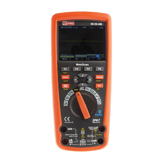
Instruction Manual
RS HS-608
Stock No: 144-5337
MeterScope
EN
PANTONE 485C
Advertisement
Table of Contents

Related Manuals for RS PRO HS-608


Summary of Contents for RS PRO HS-608
- Page 1 20 Indianapolis Street, 134 Godocho, Hodogaya, Instruction Manual Kyalami Business Park, Yokohama, Kanagawa 240-0005 Kyalami, Midrand Japan South Africa www.rs-components.com RS HS-608 www.rs-components.com U.S.A Stock No: 144-5337 Asia Allied Electronics RS Components Ltd. 7151 Jack Newell Blvd. S. MeterScope Suite 1601, Level 16, Tower 1,...
- Page 2 MeterScope/English 1.Introduction RS PRO HS-608 Professional True RMS Industrial Digital Multimeter with oscilloscope functions and TFT color LCD display, providing fast A/D conver ting sampling time, high accuracy, built-in datalogging and Trend Capture features. It can trace any interupted problems, It has bluetooth technology for data transfer and is IP67 protected.
- Page 3 MeterScope/English MeterScope/English OVERVOLTAGE CATEGORY II 3-7.NEVER operate the meter unless the back cover and the battery and fuse covers are in Equipment of OVERVOLTAGE CATEGORY II is energy-consuming equipment to be supplied place and fastened securely. from the fixed installation. Note –...
- Page 4 MeterScope/English MeterScope/English 4-4.Page Area 4-2.Understanding the Display The page area of the display is where the main meter content is displayed. The primary display (upper half of the page area) is where the most important value of the selected function is shown. The secondary display contains the bar graph and values that may be measured in addition to the primary function value.
- Page 5 MeterScope/English MeterScope/English 5-2.AC Voltage Measurements 5. Measurement and Setup WARNING: Risk of Electrocution. The probe tips may not be long enough to contact the live 5-1.DC Voltage Measurements parts inside some 240V outlets for appliances because the contacts are recessed deep in the CAUTION: Do not measure DC voltages if a motor on the circuit is being switched ON or outlets.
- Page 6 MeterScope/English MeterScope/English 5-3.Making dB Measurements 5-5.mV Voltage Measurements CAUTION: Do not measure mV voltages if a motor on the circuit is being switched ON or The Meter is capable of displaying voltage as a dB value, either relative to 1 milliwatt (dBm), OFF.
- Page 7 MeterScope/English MeterScope/English 5-6 Temperature Measurements 5-8.Resistance Measurements 1.Set the function switch to the green WARNING: To avoid electric shock, disconnect power to the unit under test and discharge TEMP( C or F) position. ° ° all capacitors before taking any resistance measurements. 2.press the soft key labeled Menu.
- Page 8 MeterScope/English MeterScope/English 5-9.Continuity Check 5-10.Diode Test WARNING: To avoid electric shock, disconnect power to the unit under test and discharge all 1.Set the function switch to the green capacitors before taking any resistance measurements. Remove the batteries and unplug Ω CAP position.
- Page 9 MeterScope/English MeterScope/English 5-11.Capacitance Measurements 5-12.DC Current Measurements WARNING: To avoid electric shock, disconnect power to the unit under test and discharge all CAUTION: Do not make 20A current measurements for longer than 30 seconds. Exceeding capacitors before taking any capacitance measurements. Remove the batteries and unplug 30 seconds may cause damage to the meter and/or the test leads.
- Page 10 MeterScope/English MeterScope/English 5-13.AC Current Measurements 5-14.Understanding Function Menus CAUTION: Do not make 10A current measurements for longer than 30 seconds. Exceeding Each primary measurement function (rotary switch position) has a number of optional 30 seconds may cause damage to the meter and/or the test leads. sub-functions or modes accessed by pressing the softkey labeled Menu (F1).
- Page 11 MeterScope/English MeterScope/English To save the MIN MAX screen data, the MIN MAX session must be ended by pressing the 5-16.Measuring AC and DC Signals softkey labeled Stop. Next, press the softkey labeled Save.A dialog box openswhere the The Meter is capable of displaying both AC and DC signal components (voltage or current) default saved name can be selected or anothername assigned.
- Page 12 MeterScope/English MeterScope/English 5-25.Recording Measurement Data 5-22.Storing Individual Measurement Data The Meter’s record feature collects measurement information over a user-specified duration. For all measurement functions, a snapshot This collection of information is called a recording session. A recording session is made up of the screen data is saved by pressing the of one or more measurement records Each record contains measurement summary information softkey labeled Save.
- Page 13 MeterScope/English MeterScope/English 5-27.Changing Meter Setup Options 5-32.Using Communications The Meter has a number of preset features such as date and time formats and battery save mode You can use the Wireless communication link and transfer the contents of a meter’s memory timeouts, and the displayed language.
- Page 14 MeterScope/English MeterScope/English 6.General Specification 5-37.Replacing the Fuses Referring to Figure , examine or replace the Meter's fuses as follows: Enclosure Double molded, waterproof 1.Turn the Meter off and remove the test leads from the terminals. Shock (Drop Test) 6.5 feet (2 meters) 2.Remove the battery door assembly by using a standardblade screwdriver to turn the battery Diode Test Test current of 0.9mA maximum, open circuit...
- Page 15 MeterScope/English MeterScope/English 7.Specifications Fuses Fuses are FF 0.8A 1000V+FF 10A 1000V Function Range Resolution Accuracy Operating Temperatur 5°C to 40°C (41°F to 104°F) Storage Temperature -20°C to 60°C (-4°F to 140°F) DC Voltage 50mV 0.001mV (0.05% + 20) Operating Humidity Max 80% up to 31°C (87°F) decreasing linearly 500mV 0.01mV...
- Page 16 MeterScope/English MeterScope/English Function Range Resolution Accuracy Function Range Resolution Accuracy AC Voltage 5K-100K DC Current 500µA 0.01µA 0.1%+20 (5000+Count) 50mV 0.001mV (5.0% + 40) 5000µA 0.1µA 500mV 0.01mV 50mA 0.001mA 0.0001V 500mA 0.01mA 0.15%+20 0.001V (6.0% + 40) 0.001A 0.3%+20 (20A: 30 sec max with reduced accuracy) NOTE: Accuracy is stated at 18 to 28°C 65 to 83°F...
- Page 17 0.01Hz 5kHz 0.0001kHz Instruction Manual 50kHz 0.001kHz 500kHz 0.01kHz RS HS-608 5MHz 0.0001MHz 10MHz 0.001MHz Stock No: 144-5337 Sensitivity: 2V RMS min. @ 20% to 80% duty cycle and <100kHz; 5V RMS min @ 20% to 80% duty cycle Oscilloscope Section and >100kHz.
- Page 18 Oscilloscope Section/English Oscilloscope Section/English General safety requirements Introduction Know the following safety precautions to avoid personal injury, also to prevent damage Digital Oscilloscope performs outstandingly, powerful, affordable, with a high cost performance. generated by connecting this product to any other product. In order to avoid any potential Its real time sample rate is up to 50 MSa/s, can meet the market needs of high capture speed, danger, please use the product according to these instructions.
- Page 19 Oscilloscope Section/English Oscilloscope Section/English Summary 1. Date and time 2. Status of current waveform windows The manual introduces operation of information of Digital Oscilloscope which includes the 3. Remaining power of battery following chapters: 4. Waveform display area • "Introduction"presents the front panel, user interface, function check and probe of the 5.
- Page 20 Oscilloscope Section/English Oscilloscope Section/English 2 2 Connector •To avoid electric shock, don’t touch the metallic part of the probe top while connecting to •The probe and connector must be used when the measuring frequecies above 1KHz. voltage source. •When measured waveform signal of DC or measuring frequency is below 1KHZ, the •Measured signal by the oscilloscope is taken as a reference voltage to the ground, make sure stick of general oscilloscope can be adopted.
- Page 21 Oscilloscope Section/English Oscilloscope Section/English 2 5 Fast/slow display 2-8-1 Trigger Mode • When the measured signal is unstable, displayed waveform presents jump; long-term •2 kinds of trigger mode for the oscilloscope: raising edge and falling edge. When signal observation may cause eye fatigue. Digital Oscilloscope offers the selection of fast/slow voltage across trigger electrical level, raising and falling edge of input signal is adopted for display function, press F3 (F/S), fast display can be switched to slow display, which can triggering.
- Page 22 Oscilloscope Section/English Oscilloscope Section/English Note: If adopt FFT (Fast Fourier Transform) mode, take following steps: •DC component or deviation existed in signal may cause error or deviation in FFT waveform 1. Set up time domain waveform component part. Select DC coupling mode to reduce AC component. •Press “AUTO”...
- Page 23 Oscilloscope Section/English Oscilloscope Section/English 2-12 Display System 4. Press F1 (V/F cursor), cursor measurement turns to voltage amplitude from frequency (cycle). Up and down cursor appears on the screen at the moment. 2 12 1 Time and Date 5. If use needs to move the cursor, press “ ”, one time for one space, press this key for •After startup, actual time and date display at the top more than 1 second for fast move, the cursor moves continuously in the same direction.
- Page 24 Oscilloscope Section/English Oscilloscope Section/English 1. Store the current displayed waveform into the device. •Press F2 (return) under waveform displaying state, turn back to “Save Operations” state. •Press “HOLD” “F2(Save)” enter into “Save Operations” state “ ” (select position) •Press “F4 (EXIT)” in waveform displaying state, turn back to waveform displaying state. →...
- Page 25 Oscilloscope Section/English Oscilloscope Section/English (5) Press “AUTO” to try again. 3 3 Serial Signal Measurement To measure serial signals, as UART, IIC, SPI and etc, please take following steps: 4.2 Waveform displays, but cannot stabilize. 1. Take 3.1 operations as reference, preliminary observe the measured signal. (1) Check the trigger option is correct or not.
- Page 26 Oscilloscope Section/English Oscilloscope Section/English Appendix 1: Daily maintenance Appendix 2:Specifications When storing the device, please don’t expose LCD display surface to direct sunlight. Main specification Format or note Function 3.5” color TFT-LCD; 320 X 240 pixels LCD display Note: Do not store in high humidity condition. 15~50 V/S Fast / Slow Refresh rate...
- Page 27 2. The measured data from Digital Multimeter can transfer to APP via bluetooth and visualize, store and log. RS HS-608 3. The measuring data can be shared with others. With Meterbox iMM, user can complete the electrical measuring, enhance measuring Stock No: 144-5337 visualization, data log &...
Need help?
Do you have a question about the HS-608 and is the answer not in the manual?
Questions and answers