Table of Contents
Advertisement
Quick Links
Download this manual
See also:
Operator's Manual
READ THIS BOOK
LEA ESTE MANUAL
LISEZ CE MANUEL
This book has important information for the use and safe operation of this machine. Failure to read
this book prior to operating or attempting any service or maintenance procedure to your Clarke
machine could result in injury to you or to other personnel; damage to the machine or to other
property could occur as well. You must have training in the operation of this machine before using it.
If your operator(s) cannot read this manual, have it explained fully before attempting to operate this
machine.
All directions given in this book are as seen from the operator's position at the rear of the machine.
For new books write to: Clarke®, 2100 Highway 265, Springdale, Arkansas 72764.
Form No. 9097182000 - 11/2009
Form No. 909 6772 000 - 05/2006
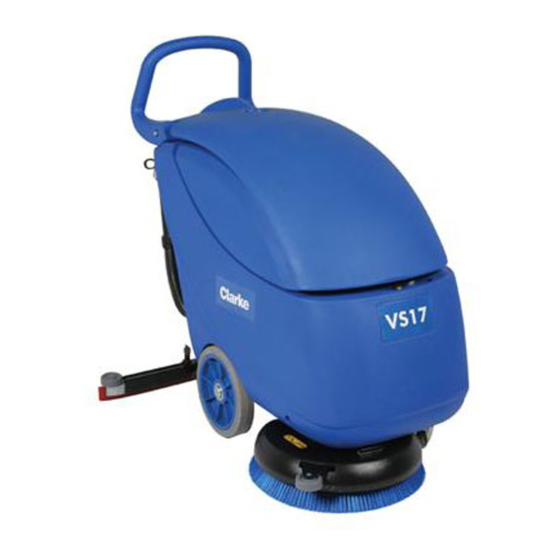
Vantage 17
Battery / Cable
Vantage 17 Battery
Operator's Manual
Manuel d'utilisation
Libro de Instrucciones
Service Manual
EN
English (3 - 27)
ES
Español (29 - 53)
FR
Français (55 - 80)
Advertisement
Table of Contents
Troubleshooting

Related Manuals for Clarke Vantage 17


Summary of Contents for Clarke Vantage 17
- Page 1 This book has important information for the use and safe operation of this machine. Failure to read this book prior to operating or attempting any service or maintenance procedure to your Clarke machine could result in injury to you or to other personnel; damage to the machine or to other property could occur as well.
-
Page 3: Table Of Contents
TROUBLESHOOTING [Vantage 17 Cable] ..................24 RECOVERY WATER SYSTEM ........................ 25 TANK AND VACUUM GRID WITH FLOAT CLEANING [Vantage 17 Battery - Cable] ......25 VACUUM SYSTEM MOTOR ELECTRICAL INPUT CHECK [Vantage 17 Battery - Cable] ....26 VACUUM SYSTEM MOTOR CARBON BRUSH CHECK AND REPLACEMENT [Vantage 17 Battery - Cable] ........................ - Page 4 ENGLISH SERVICE MANUAL OTHER SYSTEMS ........................... 32 MACHINE SPEED ADJUSTMENT [Vantage 17 Battery - Vantage 17 Cable] ........32 BRUSH/PAD-HOLDER DECK DISASSEMBLY/ASSEMBLY [Vantage 17 Battery] ......33 BRUSH/PAD-HOLDER DECK DISASSEMBLY/ASSEMBLY [Vantage 17 Cable] ....... 34 ELECTRICAL SYSTEM ........................... 36 (WET OR GEL) BATTERY REMOVAL/INSTALLATION AND SETTING [Vantage 17 Battery] ..........................
-
Page 5: General Information
Vantage 17 Battery Installation Instruction for Battery charger kit- Form Number 9097052000 Vantage 17 Battery - Vantage 17 Cable Installation Instructions for Rubber shock absorber kit - Form Number 909 6227 000 Vantage 17 Cable Instructions for Use - Form Number 909 6773 000 SAFETY Clarke uses the following symbols to indicate potentially dangerous situations. -
Page 6: General Safety Precautions
SERVICE MANUAL GENERAL INFORMATION GENERAL SAFETY PRECAUTIONS Description of potential damages to people and machine. DANGER! [Vantage 17 Battery - Cable] – This machine must be used by properly trained operators only. Children or disabled people cannot use this machine. –... - Page 7 SERVICE MANUAL ENGLISH GENERAL INFORMATION WARNING! [Vantage 17 Battery - Cable] – Do not leave the machine unattended without being sure that it cannot move independently. – Always protect the machine against the sun, rain and bad weather, both under operation and inactivity condition.
-
Page 8: Grounding Instructions
Law in force. Extension Use the extension supplied with the machine or an extension of identical electrical characteristics. 9097182000 - 11/2009 VANTAGE 17 Battery / Cable... -
Page 9: Technical Data
• max size brush deck / squeegee • solution tank full • optionals installed • weight verified on each wheel • print area verified on concrete for each wheel • result expresses as max. value for front and max value for rear wheels VANTAGE 17 Battery / Cable 9097182000 - 11/2009... -
Page 10: Maintenance
See the GENERAL INFORMATION and SAFETY paragraphs. Provided below is the Scheduled Maintenance Table. The intervals shown may vary according to particular working conditions, which are to be defined by the person in charge of the maintenance. For instructions on maintenance procedures, see the following paragraphs. SCHEDULED MAINTENANCE TABLE [Vantage 17 Battery] Daily or after Every six Procedure... -
Page 11: Machine Nomenclature
[C] Terminal board box Solution drain valve 60. Cover stand (applied) Squeegee lifting/lowering lever Solution filter [B]: Installed on Vantage 17 Battery [B] Battery charger-electrical mains connecting cable [C]: Installed Vantage 17 Cable (optional) 28a. [C] Power supply cable 28b. [C] Power supply cable extension... - Page 12 ENGLISH SERVICE MANUAL GENERAL INFORMATION VANTAGE 17 BATTERY 29 18 S301386C 9097182000 - 11/2009 VANTAGE 17 Battery / Cable...
- Page 13 SERVICE MANUAL ENGLISH GENERAL INFORMATION VANTAGE 17 BATTERY (continues) S301387 VANTAGE 17 Battery / Cable 9097182000 - 11/2009...
- Page 14 ENGLISH SERVICE MANUAL GENERAL INFORMATION VANTAGE 17 CABLE 10 13 S301388C 9097182000 - 11/2009 VANTAGE 17 Battery / Cable...
- Page 15 SERVICE MANUAL ENGLISH GENERAL INFORMATION VANTAGE 17 CABLE (continues) S301389C VANTAGE 17 Battery / Cable 9097182000 - 11/2009...
-
Page 16: Solution System
SERVICE MANUAL SOLUTION SYSTEM SOLUTION SYSTEM SOLUTION TANK CLEANING [Vantage 17 Battery - 17 Cable] Drive the machine to the appointed disposal area. Check that the switches (5 and 6) are turned to “0”. If necessary, empty the tank (44) by means of the valve (24). -
Page 17: Solution Flow Control Tap Or Solenoid Valve Disassembly/Assembly
SERVICE MANUAL ENGLISH SOLUTION SYSTEM SOLUTION FLOW CONTROL TAP OR SOLENOID VALVE DISASSEMBLY/ASSEMBLY [Vantage 17 Battery - 17 Cable] Preliminary procedures Remove the batteries. Use a protection to avoid damaging the machine and tilt it carefully to lay its right side on the floor. Solenoid valve disassembly Remove the screw (B) and disconnect the solenoid valve connector (C). Remove the screws (D) and move the solenoid valve (E). -
Page 18: Troubleshooting [Vantage 17 Battery - Cable]
ENGLISH SERVICE MANUAL SOLUTION SYSTEM TROUBLESHOOTING [Vantage 17 Battery - 17 Cable] SMALL AMOUNT OF THE SOLUTION OR NO SOLUTION REACHES THE BRUSH Possible causes: The solution filter is clogged/dirty (clean). The solution flow adjusting tap is clogged/dirty (replace). The solenoid valve is broken or there is an open in the electrical connection (replace the solenoid valve/repair the electrical connection). -
Page 19: Brushing System
SERVICE MANUAL ENGLISH BRUSHING SYSTEM BRUSHING SYSTEM BRUSH MOTOR ELECTRICAL INPUT CHECK [Vantage 17 Battery] WARNING! This procedure must be performed by qualified personnel only. Check that the brush (54) is installed on the machine. Drive the machine on a level ground. - Page 20 ENGLISH SERVICE MANUAL BRUSHING SYSTEM BRUSH MOTOR ELECTRICAL INPUT CHECK [Vantage 17 Battery] (continues) S301370 9097182000 - 11/2009 VANTAGE 17 Battery / Cable...
-
Page 21: Brush Motor Electrical Input Check [Vantage 17 Cable]
Set an ammeter (H) on the brush motor supply cable (I). Activate the brush by turning the switch (5) to “I”, then check that the brush motor electrical input is within the following limits: Vantage 17 Cable - 230 Volts, 50 - 60 Hz • with the brush on floor tiles: 4 to 5 A •... - Page 22 BRUSHING SYSTEM BRUSH MOTOR ELECTRICAL INPUT CHECK [Vantage 17 Cable] (continues) S301210 BRUSH MOTOR CARBON BRUSH CHECK AND REPLACEMENT [Vantage 17 B] (for machines before 2007/05) Remove the brush/pad-holder deck (see the procedure in the relevant paragraph). At the workbench, remove dust and dirt from the outside of the motor, then disengage and remove the clamp (A).
-
Page 23: Brush Motor Carbon Brush Check And Replacement [Vantage 17 Battery]
SERVICE MANUAL ENGLISH BRUSHING SYSTEM BRUSH MOTOR CARBON BRUSH CHECK AND REPLACEMENT [Vantage 17 B] (for machines after 2007/05) Remove the brush/pad-holder deck (see the procedure in the relevant paragraph). At the workbench, remove dust and debris from the motor, especially in the area of the carbon brushes. -
Page 24: Brush Motor And Reduction Unit Disassembly/Assembly [Vantage 17 Battery]
ENGLISH SERVICE MANUAL BRUSHING SYSTEM BRUSH MOTOR AND REDUCTION UNIT DISASSEMBLY/ASSEMBLY [Vantage 17 Battery] Motor/reduction unit disassembly/assembly Remove the brush/pad-holder (54/55), according to the instructions in the Instructions for Use Manual. Remove the brush/pad-holder deck. At the workbench, remove the central screw (A). -
Page 25: Brush Motor And Reduction Unit Disassembly/Assembly [Vantage 17 Cable]
SERVICE MANUAL ENGLISH BRUSHING SYSTEM BRUSH MOTOR AND REDUCTION UNIT DISASSEMBLY/ASSEMBLY [Vantage 17 Cable] Motor/reduction unit disassembly/assembly Remove the brush/pad-holder (54/55), according to the instructions in the Instructions for Use Manual. Remove the brush/pad-holder deck. At the workbench, remove the central screw (A). -
Page 26: Troubleshooting [Vantage 17 Battery]
The power supply cable is broken (replace). The motor is faulty (repair or replace). The brush ON/OFF switch (5) is broken (replace). The reduction unit is faulty (repair or replace). The wiring harness is damaged (repair). 9097182000 - 11/2009 VANTAGE 17 Battery / Cable... -
Page 27: Recovery Water System
ENGLISH RECOVERY WATER SYSTEM RECOVERY WATER SYSTEM TANK AND VACUUM GRID WITH FLOAT CLEANING [Vantage 17 Battery - 17 Cable] Drive the machine to the appointed disposal area. Check that the switches (5 and 6) are turned to “0”. If necessary, empty the tank (43) by means of the hose (22). -
Page 28: Vacuum System Motor Electrical Input Check [Vantage 17 Battery - Cable]
Grasp the recovery water tank (A) in the area (B) and lift it, as shown in the figure, then disconnect the vacuum hose (C) from the tank and remove the tank (A) together with the hoses (D) and (E). (Vantage 17 Cable) Loosen the clamp (I) and disconnect the hoses (J), then remove the waterproof cover (K). WARNING! Do not touch uncovered electrical components while performing the following steps. - Page 29 SERVICE MANUAL ENGLISH RECOVERY WATER SYSTEM VACUUM SYSTEM MOTOR ELECTRICAL INPUT CHECK [Vantage 17 Battery - 17 Cable] (continues) S301373 [The figure shows Vantage 17 Battery] VANTAGE 17 Battery / Cable 9097182000 - 11/2009...
-
Page 30: Vacuum System Motor Carbon Brush Check And Replacement [Vantage 17 Battery - Cable]
ENGLISH SERVICE MANUAL RECOVERY WATER SYSTEM VACUUM SYSTEM MOTOR CARBON BRUSH CHECK AND REPLACEMENT [Vantage 17 Battery - 17 Cable] Remove the vacuum system motor (see the procedure in the relevant paragraph). At the workbench, disengage the fasteners (A) and (B), then remove the cover (C) from the vacuum system motor. -
Page 31: Vacuum System Motor Disassembly/Assembly [Vantage 17 Battery - Cable]
(A) together with the hoses (D) and (E). (Vantage 17 Cable) Loosen the clamp (I) and disconnect the hoses (J), then remove the waterproof cover (K). Disconnect the vacuum system motor electrical connector (F). -
Page 32: Squeegee Disassembly/Assembly [Vantage 17 Battery - Cable]
Loosen the handwheels (18) and remove the squeegee (17). Assemble in the reverse order of disassembly. SQUEEGEE CLEANING/CHECK AND BLADE REPLACEMENT [Vantage 17 Battery - 17 Cable] CAUTION! It is advisable to use protective gloves when cleaning the squeegee because there may be cutting debris. -
Page 33: Troubleshooting [Vantage 17 Battery]
The motor is damaged (check the motor carbon brushes/electrical input). The electrical input is excessive (check the motor for proper rotation). TROUBLESHOOTING [Vantage 17 Battery - 17 Cable] DIRTY WATER VACUUMING IS INSUFFICIENT OR THERE IS NO VACUUMING Possible causes: The vacuum grid with automatic shut-off float (46) is activated because the water recovery tank (43) is full (empty the water recovery tank). -
Page 34: Other Systems
SERVICE MANUAL OTHER SYSTEMS OTHER SYSTEMS MACHINE SPEED ADJUSTMENT [Vantage 17 Battery - 17 Cable] Check that the switches (5 and 6) are turned to “0”. If there is recovery water in the tank (43), drain it through the hose (22). -
Page 35: Brush/Pad-Holder Deck Disassembly/Assembly [Vantage 17 Battery]
SERVICE MANUAL ENGLISH OTHER SYSTEMS BRUSH/PAD-HOLDER DECK DISASSEMBLY/ASSEMBLY [Vantage 17 Battery] Disassembly Remove the batteries. Remove the caps (A) and disconnect the electrical connections from the brush motor (B). Remove the left deck fastening screw (58). Use a protection (D) to avoid damaging the machine and tilt it carefully to lay its left side on the floor. Disconnect the solution hose (E) from the solenoid valve (F). -
Page 36: Brush/Pad-Holder Deck Disassembly/Assembly [Vantage 17 Cable]
ENGLISH SERVICE MANUAL OTHER SYSTEMS BRUSH/PAD-HOLDER DECK DISASSEMBLY/ASSEMBLY [Vantage 17 Cable] Disassembly Check that the switches (5 and 6) are turned to “0”. If there is recovery water in the tank (43), drain it through the hose (22). Disconnect the vacuum hose (29) from the squeegee (17). - Page 37 SERVICE MANUAL ENGLISH OTHER SYSTEMS BRUSH/PAD-HOLDER DECK DISASSEMBLY/ASSEMBLY [Vantage 17 Cable] (continues) S301377 S301222 VANTAGE 17 Battery / Cable 9097182000 - 11/2009...
-
Page 38: Electrical System
SERVICE MANUAL ELECTRICAL SYSTEM ELECTRICAL SYSTEM (WET OR GEL) BATTERY REMOVAL/INSTALLATION AND SETTING [Vantage 17 Battery] Disassembly Check that the switches (5 and 6) are turned to “0”. If there is recovery water in the tank (43), drain it through the hose (22). - Page 39 SERVICE MANUAL ENGLISH ELECTRICAL SYSTEM (WET OR GEL) BATTERY REMOVAL/INSTALLATION AND SETTING [Vantage 17 Battery] (continues) S301378 VANTAGE 17 Battery / Cable 9097182000 - 11/2009...
-
Page 40: Charging Curves Setting [Vantage 17 Battery]
SERVICE MANUAL ELECTRICAL SYSTEM CHARGING CURVES SETTING [Vantage 17 Battery] (for machines after 2007/06) Remove the plastic cap (A) in order to access to the internal DIP SWITCH. With a small screwdriver change the DIP SWICH in accordance with the below listed setting data. -
Page 41: Battery Charging [Vantage 17 Battery]
SERVICE MANUAL ENGLISH ELECTRICAL SYSTEM BATTERY CHARGING [Vantage 17 Battery] NOTE Charge the batteries when the warning light (3) or (4) turns on, or when finishing cleaning. Keeping the batteries charged makes them last longer. CAUTION! When the batteries are discharged, charge them as soon as possible, as that condition makes them last shorter. - Page 42 ENGLISH SERVICE MANUAL ELECTRICAL SYSTEM BATTERY CHARGING [Vantage 17 Battery] (continues) Battery charging with battery charger installed on the machine Connect the battery charger cable (27) to the electrical mains (the mains voltage and frequency must be compatible with the battery charger values: see the battery charger Manual).
-
Page 43: Electronic Board Replacement [Vantage 17 Battery]
SERVICE MANUAL ENGLISH ELECTRICAL SYSTEM ELECTRONIC BOARD REPLACEMENT [Vantage 17 Battery] Check that the switches (5 and 6) are turned to “0”. Remove the recovery water tank and disconnect the battery negative terminal (50) according to the following procedure: •... - Page 44 ENGLISH SERVICE MANUAL ELECTRICAL SYSTEM ELECTRONIC BOARD REPLACEMENT [Vantage 17 Battery] (continues) S301379 9097182000 - 11/2009 VANTAGE 17 Battery / Cable...
-
Page 45: Fuse Check/Replacement [Vantage 17 Battery]
SERVICE MANUAL ENGLISH ELECTRICAL SYSTEM FUSE CHECK/REPLACEMENT [Vantage 17 Battery] Check that the switches (5 and 6) are turned to “0”. Remove the recovery water tank and disconnect the battery negative terminal (50) according to the following procedure: • If there is recovery water in the tank (43), drain it through the hose (22). -
Page 46: Component Location [Vantage 17 Battery]
ENGLISH SERVICE MANUAL ELECTRICAL SYSTEM COMPONENT LOCATION [Vantage 17 Battery] Battery charger Solenoid valve and electronic board fuse (5A) Battery charger connector Negative insulator Electronic board (CF BA430) Brush/pad motor Electronic board led (CF BALED) Vacuum system motor Brush switch... - Page 47 SERVICE MANUAL ENGLISH ELECTRICAL SYSTEM COMPONENT LOCATION [Vantage 17 Battery] (continues) S301392 VANTAGE 17 Battery / Cable 9097182000 - 11/2009...
-
Page 48: Component Location [Vantage 17 Cable]
ENGLISH SERVICE MANUAL ELECTRICAL SYSTEM COMPONENT LOCATION [Vantage 17 Cable] Solenoid valve Brush/pad switch Frame Vacuum switch Brush/pad motor Right handle brush switch Vacuum system motor Left handle brush switch Plug SW1 SW2 S301393 9097182000 - 11/2009 VANTAGE 17 Battery / Cable... -
Page 49: Wiring Diagram [Vantage 17 Battery]
SERVICE MANUAL ENGLISH ELECTRICAL SYSTEM WIRING DIAGRAM [Vantage 17 Battery] (for machines before 2007/06) Key: Battery charger Battery charger connector Electronic board Electronic board LED (CF BALED) Brush switch Vacuum switch Battery charger realay Water solenoid valve Brush fuse (40A) - Page 50 ENGLISH SERVICE MANUAL ELECTRICAL SYSTEM WIRING DIAGRAM [Vantage 17 Battery] (for machines before 2007/06) (continues) S301229 9097182000 - 11/2009 VANTAGE 17 Battery / Cable...
- Page 51 SERVICE MANUAL ENGLISH ELECTRICAL SYSTEM WIRING DIAGRAM [Vantage 17 Battery] (for machines after 2007/06) Key: Battery charger Battery charger connector Electronic board Electronic board LED (CF BALED) Brush switch Vacuum switch Water solenoid valve Brush fuse (40A) Vacuum system fuse (30A)
- Page 52 ENGLISH SERVICE MANUAL ELECTRICAL SYSTEM WIRING DIAGRAM [Vantage 17 Battery] (for machines after 2007/06) (continues) S301229A 9097182000 - 11/2009 VANTAGE 17 Battery / Cable...
-
Page 53: Wiring Diagram [Vantage 17 Cable]
SERVICE MANUAL ENGLISH ELECTRICAL SYSTEM WIRING DIAGRAM [Vantage 17 Cable] Key: Solenoid valve Frame Brush/pad motor Vacuum system motor Plug Brush/pad switch Vacuum switch Right handle brush switch Left handle brush switch Color code: Black Blue Brown Green Grey Orange... -
Page 54: Eb1 Electronic Board Connections [Vantage 17 Battery]
ENGLISH SERVICE MANUAL ELECTRICAL SYSTEM EB1 ELECTRONIC BOARD CONNECTIONS [Vantage 17 Battery] S301223C Work conditions: Brush switched OFF, Vacuum switched OFF Brush switched ON, Vacuum switched OFF Brush switched OFF, Vacuum switched ON EB1 UPPER 8 WAYS MODU1 CONNECTOR (A) - Page 55 SERVICE MANUAL ENGLISH ELECTRICAL SYSTEM EB1 ELECTRONIC BOARD CONNECTIONS [Vantage 17 Battery] (continues) EB1 LOWER 8 WAYS MODU1 CONNECTOR (C) Description Work conditions Electrom. switches common Brush Electrom. Switch floating floating Vacuum Electrom. Switch floating floating - shunt + shunt <40mV (**)
- Page 57 Michigan 48071-0158 29815 John R. ALTO Cleaning Systems (UK) Ltd., Penrith (810) 544-6300 Gilwilly Industrial Estate Penrith American Lincoln / Clarke, Marietta, Georgia 30066 ® Cumbria CA11 9BN 1455 Canton Road +44 1768 868 995 (770) 973-5225 ALTO France S.A. Strasbourg B.P.
- Page 58 STATED WARRANTIES ARE IN LIEU OF ALL OTHER WARRANTIES, EXPRESSED OR IMPLIED Clarke's liability under this warranty is limited to repair of the product and/or replacement of parts and is given to purchaser in lieu of all other remedies, including INCIDENTAL AND CONSEQUENTIAL DAMAGES.
Need help?
Do you have a question about the Vantage 17 and is the answer not in the manual?
Questions and answers
where is the water cellonid located
The water solenoid valve (EV1) on the Clarke Vantage 17 is located near the electrical components. To access it, remove the batteries, protect the machine, and carefully tilt it onto its right side. Then remove the screw and connector, followed by the mounting screws. The solenoid valve is connected to hoses and can be removed after disconnecting them.
This answer is automatically generated