Table of Contents
Advertisement
Quick Links
Advertisement
Table of Contents

Related Manuals for Rotronic LOG-HC2


Summary of Contents for Rotronic LOG-HC2
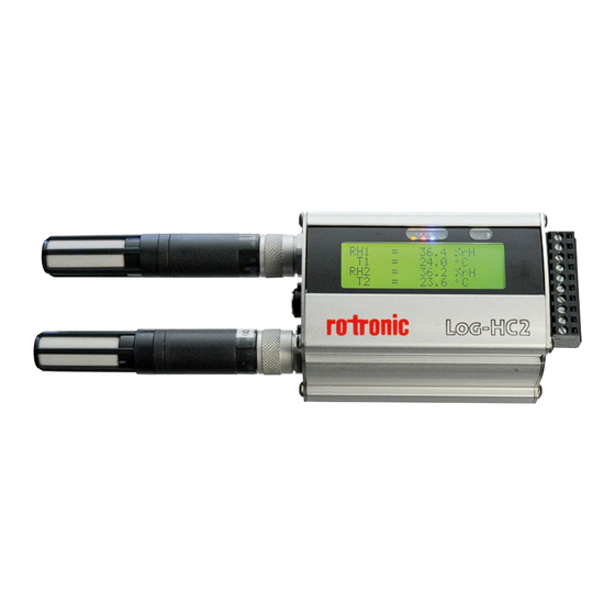
- Page 1 D-M-LOG-HC2-V1_00 Rotronic AG Bassersdorf, Switzerland Document code Unit LOG-HC2 Universal datalogger: User manual User manual Document Type Page 1 of 60 Document title LOG-HC2 Universal datalogger with LCD screen User manual © 2011; Rotronic AG EN-M-LOG-HC2-V1_00...
-
Page 2: Table Of Contents
Terminal assignment (only LOG-HC2-RO1) . . . . . . . . . . . . . . . . . . - Page 3 D-M-LOG-HC2-V1_00 Rotronic AG Bassersdorf, Switzerland Document code Unit LOG-HC2 Universal datalogger: User manual User manual Document Type Page 3 of 60 Document title Formatting the memory . . . . . . . . . . . . . . . . . . . . . . . . . . . . . . . . . . . . . . . . . . 40 Reader .
- Page 4 D-M-LOG-HC2-V1_00 Rotronic AG Bassersdorf, Switzerland Document code Unit LOG-HC2 Universal datalogger: User manual User manual Document Type Page 4 of 60 Document title Document releases Doc. Release Date Notes 28.11.2011 Original release © 2011; Rotronic AG EN-M-LOG-HC2-V1_00...
- Page 5 User manual...
- Page 6 Operating instructions PC software Setup Reader Viewer Online Utility programs Additional software for PCs...
-
Page 7: Important Notes Regarding This User Manual
Important notes regarding this user manual In this manual notes of particular importance are presented as follows: Indicates that equipment may suffer dam- WARNING age or that there is a risk of injury to the op- erator or user should the instructions not be followed correctly . -
Page 8: Safety Instructions And Warnings
. A damaged logger can endan- ger operator safety! Should the logger not function perfectly or appear to be damaged, send it to Rotronic for repair . • Ensure that no fluids enter the logger's casing . Fluids cause corrosion damage and short-circuits inside the logger . -
Page 9: Operating Instructions
Operating Instructions LOG-HC2-RO1 LOG-HC2-P1... -
Page 10: Overview
Power supply Blue: Record indicator ->32 connector Red: Alarm indicator ->31 Yellow: Battery charge indicator ->14 Light sensor* Display Analogue connections*, see page 17 for terminal assignment USB PC-Interface Push button T1 / T2 Connections for external Rotronic sensors *LOG-HC2-RO1 only... -
Page 11: Turning The Unit On / Saving Measurement Parameters
Turning the unit on / saving measurement parameters The storage properties of the logger are determined using the Setup program* . Control of measurement parameter storage can be either time activated, value activated or by pushing the push button . See also chapter „Logger display / Logger operation“... -
Page 12: Logger Display / Logger Operation
Logger display / Logger operation When the logger is turned off 1 the display cannot be activated using the T1 or T2 keys . The display and keys are activated by connecting the logger to a USB port or charger 2 . The display is operated using keys T1 and T2 (see the dia- gram "Display and operation") . -
Page 13: Logger Display And Logger Operation
Logger display and logger operation Menu 0 Menu 1 Menu 2 Menu 3 Menu 4 Record control Select predefined Select channel . . show info . . Show last se- State: on/stop by groups . . lected view . . Group indication 1 Channel Logger name,... -
Page 14: Indicator Led's
Indicator LED’s Information displayed Meaning Alarm limit reached Define the behaviour of the blue LED via Setup > Ba- Blue sic settings . See the section Setup, LED behaviour . Meaning of the yellow lamp during charging Meaning yellow Charging in progress continuously •... -
Page 15: Maintenance
Should the logger not function perfectly or should damage become apparent send the unit to Rotronic for repair . Repairs may only be carried out by Rotronic or an authorised dealer . Defective or damaged components may only be replaced with manufacturer’s original parts . -
Page 16: Specifications
Specifications See data sheets Defining the axes... -
Page 17: Terminal Assignment (Only Log-Hc2-Ro1)
Terminal assignment (only LOG-HC2-RO1) PinAssignment: GND 3VDC (switched,max.50mA) ALARM REC (ON/OFF) 10pol. NC AGND AIN4:0..5V AIN3:0..5V AIN2:4..20mA AIN1:4..20mA Alarm: •AlarmOutput 1M +3V AlarmOutput • =5V I =100mA BCR142 CMAX GND GND • AIN1...AIN4: •AnalogInput(internal)... -
Page 18: Operating, Transport And Storage Conditions
Operating, transport and storage conditions • Protect the logger from excessive exposure to the sun and other sources of heat . Avoid heavy impacts . • Do not place heavy objects on top of the logger . • Only store the logger in a dry, dust-free environment . Operating conditions: Temperature: -20°C to +65 °C... -
Page 19: Packing List
• Logger USB connection cable • Mains adapter Disposal Take the logger and the mains adapter to a municipal waste disposal centre or return it to Rotronic . The logger and the mains adapter must not be disposed of in normal domestic waste . -
Page 20: Pc Software
PC software Setup Reader Viewer Online... - Page 21 PC software Overview External processing of logger data is carried out using the LOG PC software pro- grams Setup, Reader, Viewer and Online . The LOG PC programs can be used for all logger types . The Setup enables the properties of the logger to be customised to user’s re- quirements .
- Page 22 Starting the logger Software The logger software may be started by clicking on the logger symbol or via Start > Programs > LOG_HC2 X.XX.XX (folder) > LOG_HC2 X.XX.XX . The logger program window appears: Version number of CD Logger program window Version numbers of LOG PC programs...
- Page 23 Uninstalling The software is uninstalled via the computer’s operating system (Programs > LOG_HC2 > Uninstall LOG_HC2) . System Requirements • Windows 2000 / XP / Vista / 7 • USB port...
- Page 24 Preparation Before using the LOG PC programs Setup, Reader and Online, the following preparations must be completed: • Use the USB connecting cable to connect the logger with the PC . • Before first use: Using logger symbol open the logger program window, select Settings >...
- Page 25 Template The template, selected via Setting > LOG-HC2 (* .mse), defines which sensors the Reader reads out as standard or are displayed in Online . The template sets the colour of the trace, the positioning of its axis (left, right) and gives the sensors a name (“HUM, T1”...
- Page 26 Pre-adjustments - Reader Enter the required options for the Reader** via Settings > Reader . **Data records are transferred from the logger to a PC using the Reader . Once data transfer is complete the Reader creates a data record (* .msr) from each logged record, names it and saves it in the corresponding directory .
- Page 27 Completion of the preparatory measures Upon exiting Settings the PC saves the settings that were last entered . Once entry of the settings is complete, select Programs and start the required program . Note: The following instructions assume that the preparations for using the LOG PC programs have been completed .
-
Page 28: Setup
Setup Setup is used to select the sensors for which the logger is required to save measurement parameters, to enter the measurement frequency and to set the behaviour of the logger’s memory . In Setup you can also define the start time for data recording and stop data recording . -
Page 29: Basic Settings
Basic settings This page describes the most commonly used settings – the Basic settings . Infor- mation on further settings can be found on the following pages . • Complete the preparations (->33) . • Start Setup (Setup symbol) . •... -
Page 30: Prediction
Prediction The maximum amount of data that can be re- corded is influenced by: • The number of sensors • The measurement rate • The battery capacity With each click on Prediction (Basic settings) the program generates an ap- proximate prediction using the selected basic settings . Note: The Limit settings are not taken into account here . -
Page 31: Reducing The Volume Of Data
Reducing the volume of data When making extensive recordings it is recommended that all sensors that are not required be “turned off” . This prevents unrequired measurement parameters from being saved . • Under Basic settings turn "off" all unused sensor groups (see next section) . •... -
Page 32: Led Behaviour
LED behaviour The behaviour of the blue LED is defined via Setup > Basic settings . Situation Behaviour of the blue LED Start time has First Double-flashes 5 times at 1-second been transferred 5 seconds intervals to the logger Waiting for Double-flashes at 5-second intervals start Data recording in... -
Page 33: User Settings
User settings To display the configuration saved in the logger select the Basic settings tab 1 and click Read basic settings . The settings are now displayed in the User set- tings tab . The changes made in the User settings tab CAUTION and its sub-menus will only be transferred to the logger after clicking Write user settings 2 . -
Page 34: Adjusting The Channel Properties
Adjusting the channel properties Select the tab Channels 3 in order to change the name, unit, display format and calibration of a channel . The following options are available (see following schematic): • Changing the basic unit (see page 36) Changing the factory settings (name, unit, display format) . - Page 35 Measurement value X User information Basic unit Factory settings User information Measurement value Name Name Base amplification Unit Unit Display format Display format Zero reference point Yb=X Yb = Gb * X + Ob Reference value Reference value calibration Calibration points (P1 and P2) Gs = (P2...
-
Page 36: Change Basic Unit
Change basic unit Change basic parameter is used to adapt the factory settings (name, unit, display format) to your requirements . These details are used among others, for calibration purposes . Select the desired channel (e .g . analogue input A2) and then click Changing the basic unit . -
Page 37: Calibrating The Sensors
. Calibration and adjustment of the HygroClip2 CAUTION probe is carried out using the ROTRONIC HW4 software . Select User settings and at the bottom click on Read user settings . Under General > Calibration, check the Make calibration changeable checkbox . -
Page 38: Changing The Display Parameter
Resetting the calibration to the factory defaults Uncheck the checkbox 4 (Apply calibration) and transfer the change to the logger by clicking Write user settings . If, following calibration, changes are made via CAUTION „Changing the basic unit“ on page 36, the per- formed calibration will be lost . -
Page 39: Defining The Logger Display
Defining the logger display Select Display and then click Read user settings at the bottom . Define what the device should display following a power-on-reset under Start- up . A group of measurement parameters 1 defined under Group indication , or a single channel 2 can be displayed . -
Page 40: Formatting The Memory
Formatting the memory Formtting will erase all measurement param- CAUTION eters saved in the logger! Formatting is used to delete all the measurement parameters saved in the log- ger . Formatting the logger is carried out from the Format memory tab . Deletes all measurement parameters saved in the logger... -
Page 41: Reader
Reader With the Reader users can selectively transfer data records logged with the log- ger to a PC . It does however free measurement records that have already been read out for overwriting . Transferring data records to a PC •... -
Page 42: Viewer
Viewer Records created in Reader or Online may be viewed and edited on a PC with the Viewer . The measurement parameters may be displayed either in graph or in table form . • Start the Viewer (Viewer symbol) . •... - Page 43 Move traces With right mouse button held down Enlarge section Mark the required section with the left mouse button held down . See also Graphics > Fixed axis) . Cross-hair Move axis: Grab the axis, move with left mouse button . Move centre: Grab the centre, move with left mouse button .
- Page 44 File The File menu is used to Open records , to Reopen (Open again) the most recently used records and to Save the currently open record as displayed With Save time window as the measurement pa- rameters of the displayed time window are saved . (The measurement parameters of the hidden traces are also saved) .
- Page 45 View, Graph ,Table, Configuration Graph Gridlines can be shown for each axis (bottom, left, right) . Fixed axis simplifies the amount of detail shown within a time window or range of values . • Select the required section with the left mouse but- ton held down .
- Page 46 Table (Tabelle) Go to time allows users to jump straight to the line in the table with the required time . Jump to beginning of graph causes the table to jump to the first measurement values displayed in the graph . Configuration As long as the Configuration dialog is not quit-...
- Page 47 Configuration allows the display method of the measurement parameters to be set with the help of the configuration screens . Entering title and footer information is achieved via Configuration > General . The associated sensor name, assignment to the left or right axis, the colour, line weight and style can be set for each curve .
-
Page 48: Online
Online Online allows users to view the progress of the measurement parameters directly on-screen . Procedure: • Complete the preparations ->24 . • Start Online (Online symbol) • Select the sensors that you wish to display . • Click on Next . •... - Page 49 For recurring applications in Online, Templates assist in se- lecting the required sensors and adjusting the display to suit . Create template: Start Online and select the required sen- sors . Select Next> . Use Graph > Properties, Graph > Grid line, Graph >...
-
Page 50: Utility Programs
Utility programs Cutter Calc Concat... -
Page 51: Csv
The CSV utility creates text files (* .csv or * .fmc) from data records (* .msr) . Files saved in * .csv format can subsequently be opened and edited in a word process- ing or spreadsheet application . The * .fmc files can be transferred to FreeMat1 . Creating a text file •... -
Page 52: Cutter
Cutter The Cutter utility creates an extract from a data record (* .msr) . Creating an extract from a data record • Start the Cutter utility (Logger Program window > Tool > Cutter) • Click on Start and select the data record from which the extract is to be created . -
Page 53: Calc
Calc With Calc curves from existing data records can be linked to each other using formulae and saved as a data record (* .msr) . The saved data record can be dis- played and processed in the form of curves or as a table using the Viewer . Tem- plates simplify the processing of recurring tasks . - Page 54 Modify the order of the new curves With the left mouse button pressed, drag the number field to the required position . Delete new curves Click inside the number field of the curve to be deleted and then press the delete key . Via Template > Delete plotted curve, all new curves can be simultaneously deleted .
- Page 55 Operators / brackets + - * / ^ Plus, minus, multiply, divide, to the power of Open brackets, close brackets Functions sqrt(no .) Square root of the number ln(no .) Natural logarithm of the number (base e) exp(no .) Raise basis e to the power of the number abs(no .) Absolute value of the number sgn(no .)
-
Page 56: Concat
Concat With Concat (concatenate = to link) data records can be linked together and saved as a new data record (* .msr) . The newly created data record can be dis- played and processed in the form of curves or as a table using the Viewer . Data Data New Data record 3... - Page 57 Delete all data records from the list Use Delete all to remove all data records from the list . Delete one data record from the list Select the data record to be deleted and click Delete line . Enter the name and directory for the new data record Set the path to the directory using Browse and enter the filename, or use the input window to do this .
-
Page 58: Additional Software For Pcs
Additional software for PCs FreeMat... -
Page 59: Freemat
FreeMat FreeMat is open source math software that can be installed from the logger CD (ADDITIONAL\FREEMAT) . FreeMat can be used to carry out a wide variety of calculations . How are data records transferred to FreeMat? The Reader transfers the data recorded with the logger (records) to the PC . From these data records (* .msr) CSV creates FreeMat files (* .fmc) . - Page 60 11 .2011 LOG-HC2 Firmware V1 .12 LOG-HC2 PC-Software V2 .00...
Need help?
Do you have a question about the LOG-HC2 and is the answer not in the manual?
Questions and answers