Table of Contents
Advertisement
Quick Links
Version 1.0
AT110V5 Installation Guide
1. Install the Antenna
Choose a suitable location for the antenna, with a good 'view' of the sky for optimum GPS
reception, according to the antenna type supplied:
a. AE001 – under the dashboard, adhesive side down
b. AE002 – roof mounted, requiring a hole in the panel
c. AE003 – windscreen mounted, adhesive to the glass, typically in the bottom corner of
the screen
d. AE004 – separate GPS and GSM antennas. GPS to be fitted adhesive side down and
GSM to be fitted at least 0.5m away, avoiding close proximity to metal or
loudspeakers
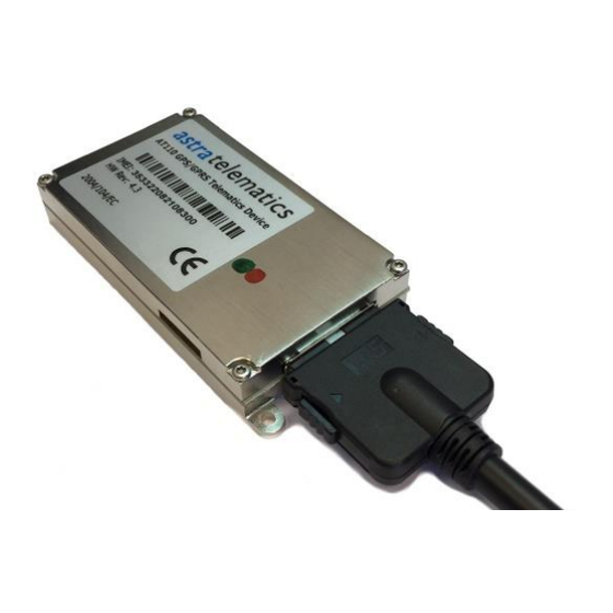
2. Plug-in the antenna GSM and GPS to the corresponding connectors on the
AT110
Apply direct force when connecting and disconnecting the antennas. Do not waggle from
side to side or apply excessive sideways force, to avoid damage to the device.
3. Hook up the power and ignition electrical connections using the CB110 cable
a. Connect the BLACK wire to GND and the RED wire to a PERMANENT +12V/+24V
vehicle power source. Connect the ignition sense input (digital input 1) to an ignition
switched 12/24V signal (i.e. something that only goes live when the vehicle ignition is
ON)
i. RED
ii. BLACK
iii. WHITE
PLUG IN ANTENNAS HERE
PERMANENT +12 / +24V
GROUND
IGNITION SWITCHED +12/24V
1A FUSED
1A FUSED
1A FUSED
Advertisement
Table of Contents

Related Manuals for astra telematics AT110V5


Summary of Contents for astra telematics AT110V5
- Page 1 Version 1.0 AT110V5 Installation Guide 1. Install the Antenna Choose a suitable location for the antenna, with a good ‘view’ of the sky for optimum GPS reception, according to the antenna type supplied: a. AE001 – under the dashboard, adhesive side down b.
- Page 2 Version 1.0 b. We recommend that all connections should be soldered to ensure reliable terminations. Crimps and IDC type terminations can be unreliable if used with the wrong tooling and/or wires sizes. 4. Plug-in the 3-way CB110 cable to the matching connector on the AT110 device Plug-in CB110 3-way cable here 5.
- Page 3 Version 1.0 7. Fit the CC001 CAN-click adapter (optional) Fit the CC001 contactless CAN-click adapter to the CANH and CANL wires and then connect the other end to the matching connector on the CB113 8. Fit the CB242 OBD adapter cable (optional) Our CB242 OBD cable provides 2 options for J1962 CANH and CANL termination: Pins 6 and 14 as per the J1962 standard (if unsure, we suggest you try this one) Pins 1 and 9...
- Page 4 Version 1.0 Note that the AT110 powers up when the SIM is fitted, both LEDs should illuminate. Note that the AT110 is fitted with an internal battery, and will power-up regardless of the external power connections, which should be verified as described in step 13 below. 11.
-
Page 5: Troubleshooting
BAT:100% GPS:OK (95%) GPRS:OK (98%) APN:OK SKT:OK ACK:OK IGN:OK (OFF) CAN:OK IMOB:OFF 14. Troubleshooting If you have any problems, questions or if you suspect a product failure / malfunction, please contact Astra Telematics technical support: support@gps-telematics.co.uk +44 161 826 8800...
Need help?
Do you have a question about the AT110V5 and is the answer not in the manual?
Questions and answers