Keithley S46 Instruction Manual
Microwave switch system
Hide thumbs
Also See for S46:
- Instruction manual (92 pages) ,
- Installation manual (6 pages) ,
- Installation manual (4 pages)

Related Manuals for Keithley S46


Summary of Contents for Keithley S46
- Page 1 S46/S46T/S46L Microwave Switch System Instruction Manual S46-901-01 Rev. F / March 2011 G R E A T E R M E A S U R E C O N F I D E N C E...
- Page 2 All rights reserved. Cleveland, Ohio, U.S.A. Document number: S46-901-01 Rev. F / March 2011 All Keithley Instruments product names are trademarks or registered trademarks of Keithley Instruments, Inc. Other brand names are trademarks or registered trademarks of their respective holders...
- Page 3 Keithley Instruments products are designed for use with electrical signals that are rated Measurement Category I and Measurement Category II, as described in the International Electrotechnical Commission (IEC) Standard IEC 60664. Most measurement, control, and data I/O signals are Measurement Category I and must not be directly connected to mains voltage or to voltage sources with high transient over-voltages.
- Page 4 To maintain protection from electric shock and fire, replacement components in mains circuits - including the power transformer, test leads, and input jacks - must be purchased from Keithley Instruments. Standard fuses with applicable national safety approvals may be used if the rating and type are the same.
-
Page 5: Table Of Contents
Table of Contents Section Topic Page General Information ............... 1-1 Introduction ....................1-1 Feature overview ..................1-1 Manual addenda ..................1-2 Specifications....................1-2 Unpacking and inspection................1-2 Inspection for damage................1-2 Shipment contents ................1-2 Repacking for shipment ............... 1-2 Available accessories ................. - Page 6 RF performance verification..............4-3 Replacing components.................4-4 Replacing relays ................... 4-4 Mainframe replacement parts ............... 4-6 Replacement precautions ..............4-6 Soldering considerations ..............4-6 Disassembly ..................4-6 Ordering information ..................4-9 Factory service .................... 4-9 Index ....................Index-1 Document number: S46-901-01 Rev. F / March 2011...
-
Page 7: General Information
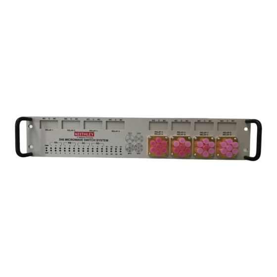
+1-440-248-0400. For worldwide contact numbers, visit the Keithley Instruments website at www.keithley.com. Feature overview The System 46 (S46) is an IEEE-488 bus controlled 19-inch rack-mounted RF relay switch controller instrument. The standard S46 configurations can accommodate eight SPDT unterminated coaxial microwave relays and four multi-pole, unterminated, coaxial microwave relays. -
Page 8: Manual Addenda
• Additional accessories as ordered Repacking for shipment Should it become necessary to return the S46/S46T/S46L for repair, carefully pack the instrument in its original packing carton or the equivalent, and follow these instructions: • Call the Repair Department at 1-800-552-1115 for a Return Material Authorization (RMA) number. -
Page 9: Sma Cables And Torque Wrench
S46-TW: SMA cable torque wrench Relay kits Relays can be added to your test system by ordering relay kits from Keithley. Each kit includes a relay, a cable assembly, any necessary hardware, and installation instructions. The installation instructions are are also provided on the CD-ROM that is supplied with the S46/S46T/S46L. -
Page 10: Replacement Relays
Available S46/S46T/S46L connections include: • Female SMA coaxial connectors for all front-panel input and output connections • Power receptacle: Standard three-prong AC line connector on rear panel • GPIB port (IEEE-488 connector) on rear panel Document number: S46-901-01 Rev. F / March 2011... -
Page 11: Installation
If installed, remove the four feet from the bottom of the S46/S46T/S46L. Retain these feet for future use. Position the S46/S46T/S46L in the rack, and loosely attach the front panel to the rack rails using the four supplied dress screws. -
Page 12: Foot Mounting
S46/S46T/S46L. Foot mounting To operate the S46/S46T/S46L on a bench, attach the supplied rubber feet to the bottom of the instrument. Each foot can be attached by removing the adhesive covering, and then pressing the foot into place in a suitable location near each corner on the bottom case cover. These feet should... -
Page 13: Connections
Handling precautions To maintain high-impedance isolation, be careful when handling the S46/S46T/S46L to avoid contamination from foreign materials such as body oils. Such contamination can reduce isolation resistance. To avoid possible contamination: •... - Page 14 4-pole or 6-pole relay connections Status LEDs System 46T 4-pole, 6-pole, XFER, or MSPDT 2-pole relay relay connections connections Status LEDs System 46L 2-pole relay connections 4-pole or 6-pole relay connections Status LEDs Document number: S46-901-01 Rev. F / March 2011...
-
Page 15: Simplified Schematic
(normally closed and normally open) and one common. • RELAY A through RELAY D on the S46 and S46T can be 4-pole, 6-pole, or MSPDT relays, each with a maximum of six inputs and one common. The number of inputs depends on relay configuration, as shown by the dotted lines in the diagram. -
Page 16: Connections
RELAY A through RELAY D connectors, as described below. Unterminated SP4T, SP6T, XFER (26.5 GHz), and unterminated 40 GHz relays have female SMA 2.9 connectors. All others have female SMA connectors. Document number: S46-901-01 Rev. F / March 2011... - Page 17 Only use 50 Ω cables specified for operation at the system frequency (18 GHz, 26.5 GHz, or 40 GHz). Relay configuration The S46/S46T/S46L can be populated with relays as follows: • RELAY A, B, C, and D can be populated with either 4-pole or 6-pole relays. The S46T can also accommodate up to four transfer switches (DPDT), MSPDT, and unterminated SP4T and SP6T relays.
-
Page 18: Gpib Control Connection
The rear-panel, IEEE-488 (GPIB) control port is connected to the GPIB port of a computer (controller) using a shielded IEEE-488 interface cable with metric mating screws. Figure 2-5 shows the GPIB control connector, and Table 2-2 summarizes the GPIB control connector terminals. Document number: S46-901-01 Rev. F / March 2011... - Page 19 Line up the cable connector with the IEEE-488 connector located on the rear panel of the S46/S46T/S46L. The connector’s design allows installation to the port in only one position. Secure the connector by tightening the screws firmly (do not overtighten).
-
Page 20: Power Connections
Power connections Line voltage The S46/S46T/S46L operates from a line voltage in the range of 100 V to 240 V at a frequency of 50 Hz or 60 Hz. Line voltage selection is automatic. CAUTION Operating the S46/S46T/S46L on an incorrect line voltage may cause damage, possibly voiding the warranty. - Page 21 Line fuse replacement A rear-panel fuse protects the power line input of the S46/S46T/S46L. If the line fuse need to be replacemed, perform the steps below. Disconnect the line cord from the instrument before changing the WARNING line fuse.
- Page 22 Table 2-4 Power supply fuse Line voltage Fuse rating Keithley part number 100 V to 240 V 1.6 A slow blow, 250 V, 5 mm x FU-106-1.6 20 mm 2-10 Document number: S46-901-01 Rev. F / March 2011...
-
Page 23: Ground Connection
(Figure 2-2) should be connected to safety earth ground using #18 AWG or larger wire if the S46/S46T/S46L is not mounted in a properly grounded rack. Switching considerations Signals switched by the S46/S46T/S46L may be subject to various effects that can seriously affect their integrity. -
Page 24: Voltage Standing Wave Ratio
The voltage standing wave ratio (VSWR) is a measurement of mismatch in a cable, waveguide, or antenna system. The measurement is shown as ratio to 1 (for example, a VSWR of 1.2 is actually the ratio of 1.2:1). Refer to the specifications located on the Keithley Instruments website (www.keithley.com/support) for S46/S46T/S46L VSWR information. -
Page 25: Operation
• Errors Signal considerations WARNING Maximum voltage between any conductor and ground is 42V. To prevent damage to the S46/S46T/S46L, do not exceed the maximum CAUTION signal level specifications of the switch. Maximum signal level specifications • Maximum voltage: 30 V DC, 42 V peak •... -
Page 26: Bus Connections
S46/S46T/S46L Microwave Switch System Instruction Manual Bus connections Before using the S46/S46T/S46L, you must connect the IEEE-488 connector on the rear panel of the switch to the IEEE-488 connector of the controller. Use a Keithley Instruments Model 7007 or similar shielded IEEE-488 cable for this connection. Refer to... - Page 27 Each command string is separated by a semicolon (;). The following example uses the short-form format to reduce the size of the message: :ROUT:CLOS (@1,7);:ROUT:CLOS? The above program message closes channels 1 and 7, and then queries for closed relays. Document number: S46-901-01 Rev. F / March 2011...
- Page 28 Each program message must be terminated with an LF (line feed), EOI (end or identify), or an LF + EOI. The bus will stop responding if your computer does not provide this termination. The following example shows how a program message must be terminated: open:all <PMT> Document number: S46-901-01 Rev. F / March 2011...
-
Page 29: Response Messages
After sending a query command, the response message is placed in the output queue. When the relay unit is then addressed to talk, the response message is sent from the output queue to the computer. Document number: S46-901-01 Rev. F / March 2011... -
Page 30: Gpib Commands
Message exchange protocol Two rules summarize the message exchange protocol: Rule 1: You must always tell the S46/S46T/S46L what to send to the computer. Perform the following two steps to send information from the instrument to the computer: Send the appropriate query command(s) in a program message. - Page 31 (the number of times the channel has been closed). Unpopulated channels always have a count of zero. To reset this count, see :RCOunt <clist> Reset closure count for channels. Document number: S46-901-01 Rev. F / March 2011...
- Page 32 A through D. Terminated SP4T relays are programmed with a value of 6. Ports 2, 3, 5, and 6 control channels are used. Query This query returns the relay configuration pole information with the form factor defined above. Document number: S46-901-01 Rev. F / March 2011...
-
Page 33: Status Commands
Table 3-8. commands are used to control STATus STATus the status registers of the S46/S46T/S46L. Following the table are details defining the use of the specific subsystem commands. STATus NOTE Status model later in this section for more details. - Page 34 Use this query to read messages placed in the error queue. For example, send: :STAT:QUE:NEXT? After this command is sent and the S46/S46T/S46L is addressed to talk, the oldest message in the queue is sent to the computer. The queue holds up to 10 messages. The error queue is a FIFO (first-in, first-out) register.
-
Page 35: System Commands
:SYSTem subsystem command set Commands Description Root path to :SYSTem subsystem commands :SYSTem Query system error queue :ERRor? Query SCPI version :VERSion? Clear messages in error queue :CLEar Query the serial number only :SNUMber? Document number: S46-901-01 Rev. F / March 2011 3-11... -
Page 36: Status Model
:VERsion? Query SCPI version Description Use this query to read the version of the SCPI standard being used by the S46/ S46T/S46L. For example, send: :SYST:VER? :CLEar Clear all messages from the error queue Description Use this command to clear all messages from the error queue. -
Page 37: Event Register Sets
When an event register bit is set and its corresponding enable bit is set (as programmed by the user), the output (summary) of the register will set to 1, which in turn sets the summary bit of the Status Byte Register. Document number: S46-901-01 Rev. F / March 2011 3-13... -
Page 38: Enable Registers
(this queue holds up to 10 messages). When a queue contains data, it sets the appropriate summary bit of the Status Byte Register. 3-14 Document number: S46-901-01 Rev. F / March 2011... - Page 39 0, No Error in the queue. Messages in the error queue are preceded by a code number. Negative (-) numbers are used for SCPI defined messages, and positive (+) numbers are used for Keithley-defined messages. The error messages are listed in Table 3-14.
-
Page 40: Status Byte And Srq
Status byte and SRQ Service request is controlled by two 8-bit registers: The Status Byte Register and the Service Request Enable Register. Figure 3-12 shows the structure for these registers. 3-16 Document number: S46-901-01 Rev. F / March 2011... - Page 41 Status Byte Register. When a summary bit of the status byte is set and its corresponding enable bit is set (as programmed by the user), the RQS/MSS bit will set to indicate that an SRQ has occurred. Document number: S46-901-01 Rev. F / March 2011 3-17...
-
Page 42: Service Request Enable Register
Clearing registers and queues When the S46/S46T/S46L power is turned on, the bits of all registers in the status structure are clear (set to 0) and the two queues are empty. Commands to reset the event and event enable... -
Page 43: Programming Enable Registers
B3, and B2, the parameter value would be the sum of the decimal weights for those bits (32+16+4 = 52). Table 3-12 16-bit status register Bit position B7 Binary value 0/1 Decimal weights 128 Document number: S46-901-01 Rev. F / March 2011 3-19... -
Page 44: Reading Registers
Status byte query Read the Status Byte Register. *STB? Self-test query Perform a checksum test on ROM and returns the result. *TST? Wait-to-continue command Wait until all previous commands are executed. *WAI 3-20 Document number: S46-901-01 Rev. F / March 2011... - Page 45 (enabled), the occurrence of any one of them causes the ESB bit in the Status Byte Register to set. Read the Standard Event Status Register using the query *ESE? command. Document number: S46-901-01 Rev. F / March 2011 3-21...
- Page 46 Standard Event Status Register are set. These bits indicate that a device-dependent error and command error have occurred. The bits of the Standard Event Status Register are described as follows: 3-22 Document number: S46-901-01 Rev. F / March 2011...
- Page 47 • Bit B6: Not used. • Bit B7, power on (PON): A set bit indicates that the S46/S46T/S46L has been turned off and turned back on again since the last time this register has been read. *IDN? - identification query...
- Page 48 Event: ESB = Event Summary Bit MAV = Message Available Bit EAV = Error Available MSB = Measurement Summary Bit Value: 1 = Enable Service Request Event 0 = Disable (Mask) Service Request Event 3-24 Document number: S46-901-01 Rev. F / March 2011...
- Page 49 • Bit 4, message available (MAV): A set bit indicates that a message is present in the output queue. The message is sent to the computer when the S46/S46T/S46L is addressed to talk. • Bit 5, event summary bit (ESB): A set bit indicates that an enabled standard event has occurred.
-
Page 50: Errors
-214 Trigger deadlock -213 Initialization ignored -212 Arm ignored -211 Trigger ignored -210 Trigger error -200 Execution error EE = error event SE = status event SYS = system error event 3-26 Document number: S46-901-01 Rev. F / March 2011... - Page 51 Invalid separator -102 Syntax error -101 Invalid character -100 Command error +000 No error +900 Internal system error EE = error event SE = status event SYS = system error event Document number: S46-901-01 Rev. F / March 2011 3-27...
-
Page 52: Service Information
Do not touch areas adjacent to electrical contacts. • When servicing the instrument, wear clean cotton gloves. • Do not store or operate the S46/S46T/S46L in an environment where dust could settle on the circuit board. Circuit board and connector cleaning •... -
Page 53: Coaxial Switch Performance Verification
28° C, and at a relative humidity of less than 70 percent. Recommended equipment Table 4-15 summarizes the equipment necessary for performance verification (channel resistance tests). Required cables and multimeter may be purchased from Keithley Instruments. Table 4-15 Recommended verification equipment Manufacturer/Model Equipment description (Qty) Specifications 10 Ω... -
Page 54: Rf Performance Verification
RF performance verification Use a vector network analyzer (VNA) to verify switch RF performance. Refer to VNA operating instructions. Relay specifications are listed in the product specifications located on the Keithley Instruments website (www.keithley.com/support). Document number: S46-901-01 Rev. F / March 2011... -
Page 55: Replacing Components
>> Replacing components Replacing relays You can replace defective relays without removing the top cover of the S46. To obtain a replacement relay, order the applicable relay kit. Table 4-16 lists the part numbers for the relays that can be ordered from Keithley Instruments. - Page 56 S46/S46T/S46L Microwave Switch System Instruction Manual Section 4: Service Information NOTE Make sure that you order the relay kit for the applicable system (S46, S46T, or S46L). Relay kits contain components and instructions appropriate for your specific system. Table 4-16...
-
Page 57: Mainframe Replacement Parts
After cleaning, allow the card to dry in a 50° C low-humidity environment for several hours before use. Disassembly To disassemble the S46/S46T/S46L in order to gain access to and replace the relays or other components, perform the following steps (refer to Figure 4-17... - Page 58 Remove the screws that secure the power supply to the chassis, then remove the power supply. To assemble the S46/S46T/S46L, reverse the disassembly instructions. Make sure all parts are properly seated and secured, and that all connections are made properly.
- Page 59 S46/S46T/S46L Microwave Switch System Instruction Manual Figure 4-19 S46T exploded view NOTE Refer to Figure 4-2 for exploded views of Digital board, Power supply, Power module, and Rear cover. Top cover Relays Relays Document number: S46-901-01 Rev. F / March 2011...
-
Page 60: Ordering Information
Component designation (if applicable) • Keithley part number Factory service If you need to return your S46/S46T/S46L to Keithley Instruments for repair, perform the following: • Call the Repair Department at 1-800-552-1115 for a Return Material Authorization (RMA) number. •... -
Page 61: Index
........2-8 Error queue ..........3-15 Program message terminator (PMT) ..3-4 Event register sets ........3-13 Programming enable registers ....3-19 Example command ........3-4 Programming syntax ........ 3-2 Exploded view ......4-7 Document number: S46-901-01 Rev. F / March 2011 Index-1... - Page 62 Soldering considerations ......4-6 Specifications ...........1-2 Status byte and SRQ ......3-16 Status Byte Register .......3-17 Status model ..........3-6 Switching considerations ......3-26 Unpacking and inspection ......1-2 VERsion? ..........3-12 Voltage Standing Wave Ratio ....2-12 Index-2 Document number: S46-901-01 Rev. F / March 2011...
- Page 63 M E A S U R E C O N F I D E N C E Keithley Instruments, Inc. Corporate Headquarters • 28775 Aurora Road • Cleveland, Ohio 44139 • 440-248-0400 • Fax: 440-248-6168 • 1-888-KEITHLEY • www.keithley.com 12/06...
Need help?
Do you have a question about the S46 and is the answer not in the manual?
Questions and answers