Advertisement
Table of Contents
OPERATING & SERVICE PARTS MANUAL
Model SM-1
READ ALL INSTRUCTIONS CAREFULLY BEFORE OPERATING EQUIPMENT
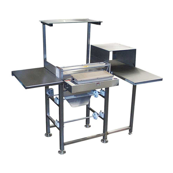
SCALEMATE OVERWRAPPER
Model SM-1 with 12 Hour Timer,
Right and Left wings, Printer
Shelf and PS20 Label Dispenser
Model SM-1 with Left Wing,
Right Wing with Hood, and
All purpose Shelf.
Revised 2017
Advertisement
Table of Contents

Related Manuals for HeatSeal SM-1


Summary of Contents for HeatSeal SM-1
- Page 1 Model SM-1 Model SM-1 with Left Wing, Right Wing with Hood, and All purpose Shelf. Model SM-1 with 12 Hour Timer, Right and Left wings, Printer Shelf and PS20 Label Dispenser READ ALL INSTRUCTIONS CAREFULLY BEFORE OPERATING EQUIPMENT Revised 2017...
-
Page 2: Table Of Contents
TABLE OF CONTENTS Operating Instructions ....................3 Film Threading & Mounting ..................4 Recommended Maintenance ..................5 Scalemate Schematic & Parts List ................6 Troubleshooting Guide ....................7 Electrical Service Information ..................8 Hot Plate Schematic & Parts List ................. 9 Electrical Schematics &... -
Page 3: Operating Instructions
OPERATING INSTRUCTIONS OPERATION First, mount and plug in any accessories you plan on using with your Scalemate. The accessory outlet is located midway up on the left side of the frame. Next, plug your Scalemate wrapper into the appropriate power supply. The standard Scalemate wrapper utilizes a 115 volt AC power supply. -
Page 4: Film Threading & Mounting
Thread the film as shown, one at a time or as needed. FILM SELECTOR Pull different sized films into film selector and drape un- used film in front of roller. MODEL SM-1 MOUNTING FILM ON AXLE Loosen four wing nuts (A) Swing out upper bearing blocks (B) on both sides... -
Page 5: Recommended Maintenance
RECOMMENDED MAINTENANCE MAKE SURE TO TURN OFF THE UNIT, PULL THE PLUG AND LET THE MACHINE COOL DOWN BEFORE CLEANING * NON-STICK COVER & HOT PLATE It is recommended to replace the Non-stick cover at least once every three months to protect the heating foil and maintain a sanitary surface. -
Page 6: Scalemate Schematic & Parts List
SCALEMATE REPLACEMENT PARTS ITEM PART # DESCRIPTION 1903077 SCR, MACH, PAN HD, SLOT, SS, 8-32 X 3/8 LG. 1905021 SCR, SET, SOCKET, CUP PT, 8-32 X 1/4, BLACK 1905055 Screw, Self Tap, Type 23 8-32 x 1/2 2105009 BEARING, FLANGE, NYLON, 5/16 ID. X 1/2 OD. X 1/2 LG. 2105057 BEARING, FLANGED, BRONZE, 2150011 Decal, Film Tension Tightness 2150143 LABEL, THREADING DIAGRAM... -
Page 7: Troubleshooting Guide
TROUBLESHOOTING OVERWRAPPERS GENERAL QUESTIONS If new machine doesn't turn on (heat up) what Ensure power switch is ON. Check if fuse is blown. Check for loose wires in should we do? the electrical box, shipping may loosen wire connections. My unit is tripping the GFCI? The wires in the hot plate may be shorting and should be insulated with a high temperature electrical tape. -
Page 8: Electrical Service Information
ELECTRICAL SERVICE INFORMATION ELECTRICAL REQUIREMENTS All Models are 110 Volts, 10 Amps. HOT ROD CIRCUIT BOARD TEST A standard 115 volt neon circuit tester can be used for these tests. CHECKING FUSES Remove the fuse from their housing units located on the front of the electrical box. If a visual inspection does not verify a blown fuse check for continuity by using the meter to read across the two terminals of the fuse. -
Page 9: Hot Plate Schematic & Parts List
ELECTRICAL SCHEMATICS & PARTS WARNING: MAKE SURE THE MACHINE IS UNPLUGGED AND HEATING ELEMENTS ARE COOL BEFORE SERVICING. ACCESSING ELECTRICAL COMPONENTS The electrical components are located in the electrical enclosure below the hot plate. To access the compo- nents, unscrew the six screws (A) on the bottom of the electrical enclosure. -
Page 10: Electrical Schematics & Replacement Instructions
ELECTRICAL DIAGRAM & CIRCUIT BOARD REPLACING THE FUSE 1. To replace the fuse, locate the fuse holder on the back left portion of the FOR MODEL SM-1 electrical enclosure next to the pow- er cord. 2. Push in slightly and twist counter- clockwise until holder and fuse pop out. -
Page 11: Replacing The Hot Rod
REPLACING THE HOT ROD REPLACING THE HOT ROD Tools needed: Medium Phillips Screwdriver 5/16 Allen Wrench 1. To replace the hot rod, unplug the machine and let the hot rod and hot plate cool down. 2. Once the hot rod is cool, remove the access panel on the bottom of the electrical en- closure (See “Accessing Electrical Components”). -
Page 12: Replacing The Hot Plate Heating Element
REPLACING THE HOT PLATE ELEMENT REPLACING THE HOT PLATE HEATING ELEMENT Tools Needed Medium Phillips Screwdriver Medium Flathead Screwdriver 7/16 Wrench To replace the hot rod, unplug the machine and let the hot rod and hot plate cool down. Once the hot rod is cool, remove the access panel on the bottom of the electrical enclosure (See “Accessing Electrical Components”).
Need help?
Do you have a question about the SM-1 and is the answer not in the manual?
Questions and answers