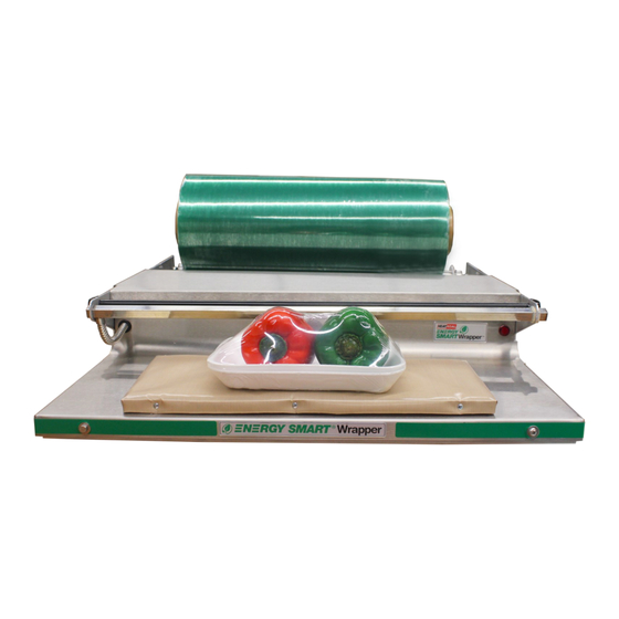
HeatSeal 700ES Operating & Service Parts Manual
Energy smart wrapper
Hide thumbs
Also See for 700ES:
- Operating & service parts manual (13 pages) ,
- Operating & service parts manual (10 pages)
Subscribe to Our Youtube Channel
Summary of Contents for HeatSeal 700ES
- Page 1 OPERATING & SERVICE PARTS MANUAL 700ES ENERGY SMART WRAPPER SERIES C READ ALL INSTRUCTIONS CAREFULLY BEFORE OPERATING EQUIPMENT Revised 2018...
-
Page 2: Table Of Contents
TABLE OF CONTENTS Machine Components & Electrical Requirement ............3 Preliminary Setup ......................5 Recommended Maintenance ..................6 Troubleshooting Guide ....................7 Heater Control Board Assembly ................... 9 Service Parts Information ................... 10 Revised 2018... -
Page 3: Machine Components & Electrical Requirement
This feature ensures that the seal plate will consume energy only when there is a demand by the operator. ELECTRICAL REQUIREMENT The Model 700ES requires 115 volts, 15A Circuit. Revised 2018... - Page 4 MACHINE TECHNOLOGY & COMPONENTS STAINLESS STEEL BRIDGE The stainless steel bridge is not recommended as a cutting surface and should not be used as one. INDICATOR LIGHT The LED light near the center of the unit (2) illuminates to indi- cate that the heat cycle is in process.
-
Page 5: Preliminary Setup
PRELIMINARY SETUP FILM THREADING Film threading is important to achieve proper film tensioning. Proper film tensioning allows for the easiest cutting of film. Facing the tension knob (1) side of the machine, the film should come off the roll counter-clockwise and route down and between the two rollers. -
Page 6: Recommended Maintenance
Wipe the surface clean of debris and residue with clean paper towels or cloths and repeat as needed. CLEANING THE UNIT The 700ES can be wiped down using mild cleaning detergent and a soft cloth or paper towels. DO NOT HOSE DOWN OR SUBMERSE THE UNIT. -
Page 7: Troubleshooting Guide
3) Reset new GFCI. Red Power Light at right front of unit SHOULD glow. 4) If GFCI trips, seal plate may have moisture inside. Allow 1-2 days to dry out and then retry. Figure 1 700ES Electrical Box Pictured Revised 2018... - Page 8 TROUBLESHOOTING Symptom Possible Solution Unit has power Verify power. Does the LED light turn ON when photo eye is triggered? but the Seal Plate 1) If neither the LED or Seal Plate work, verify that the 20 Amp Circuit Breaker has not does not work tripped.
-
Page 9: Heater Control Board Assembly
HEATER CONTROL BOARD ASSEMBLY 120 VAC NEUTRAL HEATER OUT PRODUCT DETECTION (+) THERMISTOR (-) THERMISTOR Revised 2018... -
Page 10: Service Parts Information
SERVICE PARTS INFORMATION BILL OF MATERIALS FOR MAJOR SUB-ASSEMBLIES ITEM QTY PART NUMBER DESCRIPTION 5901-011 Non-stick Cover, 6 x 15 6137-149 Replacement 6 x 15 Seal Plate Kit 6137-094 Hot Rod Replacement Kit Includes: (1) Square Cutoff Rod, (1) Rubber Grommet, (1) Size 206 O-Ring 6340-064 Vinyl Replacement Kit Includes: (1) Film Retainer, (2) Black Plastic Shaft Retainer 6340-066... - Page 11 ELECTRICAL BOX & HOT PLATE PARTS BILL OF MATERIALS FOR ELECTRICAL BOX ITEM QTY PART NUMBER DESCRIPTION 1818-035 Circuit Board Assembly, Energy Smart Wrappers 6340-070 Circuit Board Mounting Kit Includes: (4) Plastic Clip Stand-Offs 1875-055 Terminal Block 1815-030 1A Circuit Breaker 1815-031 20A Circuit Breaker 1872-123...


Need help?
Do you have a question about the 700ES and is the answer not in the manual?
Questions and answers