Table of Contents
Advertisement
Quick Links
Download this manual
See also:
Instruction Manual
Advertisement
Table of Contents

Related Manuals for RCA MRM400

Summary of Contents for RCA MRM400
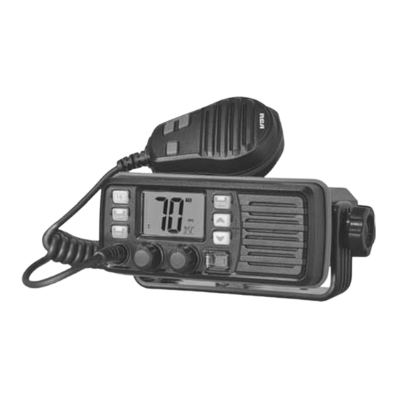
- Page 1 VHF Marine Two-Way Radio...
- Page 2 TO USER: CAUTION Thank you for purchasing this marine radio. You will fi nd the professional and human oriented design of the trans- Never use the Distress call when your ship or a person is not in an emergency. ceiver during use.
-
Page 3: Table Of Contents
C O N TEN T S PREPARATION DSC OPERATION Supplied accessories................1 MMSI code programming ..............12 Transceiver mounting ................1 MMSI code check .................12 Antenna connection ................2 DCS address ID..................12 Connections...................2 Distress call ..................13 Dimensions ....................3 Individual call ..................14 PANEL DESCRIPTION Group call .....................16 All Ships call ..................17 Front panel ....................4 Geographical Area call .................18... -
Page 4: Preparation
P REPARAT I O N Supplied accessories Transceiver mounting The following accessories are supplied: Using the supplied mounting bracket The universal mounting bracket supplied with your transceiver allows overhead or dashboard mounting. ITEM Fix the mounting bracket to shelf or dashboard with the supplied screws and DC power cable mount the transceiver to the mounting bracket with the knob bolts. -
Page 5: Antenna Connection
Embedded mounting Cut a hole into the instrument panel (or wherever you plan to mount the transceiver). Slide the transceiver through the holes as shown below. Antenna connection Please connect an antenna before transmitting. Select the antenna with the relative frequency and connect on the ANT antenna connector. -
Page 6: Dimensions
DC15A/32V. Dimensions External speaker lead Connect to an external speaker. GPS receiver lead Connect to a GPS receiver for position indication. An NMEA0183 ver.2.0 or 3.01 (sentence formatters RMC, GGA, GNS, GLL) compatible GPS receiver is required. ... -
Page 7: Panel Description
PAN E L DESCR I P T I O N 3. DSC / Position Key Front panel → Push to enter DSC menu. → Push and hold for 1 sec. to show the current position from a GPS receiver. 4. -
Page 8: Microphone
Microphone Function display Channel Number Readout → Indicate the selected operating channel number. (Refer to channel list) [PTT] → In set mode, indicate the selected condition. Push and hold to transmit; release to receive. Channel Group Indicator Channel UP / DOWN Keys[▲]/[▼] Indicate whether a U.S.A. - Page 9 call is received. GPS Indicator → Appears while valid position data is received. → Blinks when invalid position data is received. → Disappears when no GPS receiver is connected. Weather Channel Indicator → “WX” appears when a weather channel is selected. →...
-
Page 10: Basic Operation
BAS I C O PERAT IO N Power ON / OFF Channel group selection Rotate [VOL] clockwise to turn power on; The transceiver is pre-programmed with 59 U.S.A., 59 international and 63 Cana- dian channels. These channel groups may be specifi ed for the operating area. Rotate [VOL] counter-clockwise to turn power off. -
Page 11: Call Channel Programming
[16] momentarily to select Channel 16. Push “WX” appears when a weather channel is selected. “WX ALT” appears when the weather alert function is in use. [CH/WX] to return to the condition before selecting Channel 16, or Push push [▲] or [▼] to select operating channel. -
Page 12: Channel Comments
microphone. This prevents accidental channel changes and function access. → While pushing and holding [HI/LO] on the microphone, turn power ON to toggle the microphone lock function ON and OFF. Display backlighting Channel comments The function display and keys can be backlit Memory channels can be labeled with a unique alphanumeric ID of up to 10 char- for better visibility under low light conditions. -
Page 13: Scan Operation
S CA N O PERAT IO N [U/I/C] (both [▲] and [▼]) several times to select the desired channel Push Scan types group. The transceiver has priority scan and normal scan. (Refer to set mode program- Select the desired channel to be set as a TAG channel. ming). -
Page 14: Dual-Watch / Tri-Watch
DUAL -W ATCH / TR I- W ATC H Operation Description Select Dualwatch or Tri-watch in set mode. The transceiver has Dualwatch and Tri-watch. Select the desired channel. Dualwatch monitors Channel 16 while you are receiving on another channel. [CH/WX] for 1 sec. -
Page 15: Dsc Operation
DS C O PERAT I O N MMSI code programming The 9-digit MMSI (Maritime Service Identity: DSC self ID) code can be programmed at power ON. [VOL] to turn power OFF. Rotate [DSC], turn power ON to enter MMSI code pro- While pushing and holding Check the 9-digit MMSI (DSC self ID) code. -
Page 16: Distress Call
When no address ID is programmed, “NO ID” is displayed. [▲] or [▼] to input 9-digit of the appropriate address ID. Push [▲] or [▼] to select the desired ID name for deleting and push [DSC], Push Push [16] or [CH/WX] to move the cursor forward or backward, respec- “READY”... -
Page 17: Individual Call
“DSC” appears and “RCV DISTRESS ACK” scrolls at the channel com- ment indicator, then Channel 16 is automatically selected. After receiving the acknowledgment, reply using the microphone. “RCV DISTRESS ACK” scrolls at the channel comment indicator. [DISTRESS] for 5 sec. to transmit a re-newed Distress call, Push and hold Receiving a Distress Relay call ... - Page 18 [DSC] to select the desired pre-programmed individual address using Push When the acknowledgement ‘Able to comply’ is received, the specifi ed chan- [▲] or [▼], then push [DSC]. nel (in step ③) is selected with beeps automatically. Or, when the acknowl- ...
-
Page 19: Group Call
The emergency alarm or beeps sound depending on the received category. “DSC” appears and “RCV INDIVIDUAL” scrolls at the channel comment in- dicator. Push any key to stop beep. [DSC] to reply the call and select the channel specifi ed by the calling Push station for voice communication;... -
Page 20: All Ships Call
[▲] or [▼] to select the desired intership channel, and push [DSC]. Push Push any key to stop beep. Channel 70 is selected and “READY” appears. [DSC] to select the channel specifi ed by the calling station for voice Push communication;... -
Page 21: Geographical Area Call
Receiving a Geographical Area call Low power is selected. While monitoring Channel 70 and a Geographical Area call (for the area you are in) is received: The emergency alarm or beeps sound depending on the received category. “DSC” appears and “RCV GEOGRAPHICAL” scrolls at the channel comment indicator. - Page 22 Transmitting Position Request call “WAIT ACK” scrolls at the channel comment indicator. Transmit a Position Request call when you want to know a specifi ed ship’s cur- rent position, etc. [DSC] to enter the DSC menu. Push [▲] or [▼] to select “POS REQUEST”, then push [DSC]. Push Push any key to exit the condition and return to the normal operation.
- Page 23 [DSC] to reply to the call; Push any other key to ignore the call. Push The ‘Latitude’ and ‘Longitude’ from the called station is displayed and scrolled automatically in order of Latitude co-ordinates and then Longitude co-ordinates after replying the call. After the Position Report call has been transmitted, stand by on Channel 70 until an acknowledgement is received.
-
Page 24: Set Mode
SET M O D E The transceiver has 2 scan types: Normal scan and Priority scan. Normal scan Set mode programming searches all TAG channels in the selected channel group. Priority scan searches all TAG channels in sequence while monitoring Channel 16. Set mode is used to change the conditions of the transceiver’s functions: Scan type (Normal or Priority), Scan resume timer, Weather alert, Dual/Tri-watch, DSC watch, Scan resume timer... - Page 25 You can select silent operation by turning beep tones OFF or you can have con- fi rmation beeps sound at the push of a key by turning beep tones ON. Automatic acknowledgement This item sets the Automatic acknowledgement function ON or OFF. When Position Request call or Position Report call is received, transceiver au- tomatically transmits Position Request Reply call or Position Report Reply call, respectively.
-
Page 26: Channel List
CHANNEL LIST Channel number Frequency(MHz) Channel number Frequency(MHz) Channel number Frequency(MHz) Channel number Frequency(MHz) CAN Transmit Receive CAN Transmit Receive CAN Transmit Receive CAN Transmit Receive 156.050 160.650 157.050 161.650 156.425 156.425 157.325 157.325 156.050 156.050 157.050 157.050 156.475 156.475 157.375 161.975... -
Page 27: Specifications
SPECIFICATIONS Transmitter Receiver General ≤0.2uV Output power 25W / 1W Sensitivity TX: 156.025-157.425 MHz ≤0.2uV Max. frequency deviation ±5.0 kHz Squelch sensitivity Frequency coverage ≤-70dB (H) ≥70dB RX: 156.050 -163.275 MHz Adjacent channel selectivity Spurious emissions ≤-56dB (L) ≥70dB Mode FM (16K0G3E) DSC (16K0G2B)
Need help?
Do you have a question about the MRM400 and is the answer not in the manual?
Questions and answers