Table of Contents
Advertisement
Test report no. 17010729
EUT: ID ISC.ANT1520/680 (RFID gate)
Date: 2016-08-19
m. dudde hochfrequenz-technik
Page 1 of 1
FCC ID:
PJMLRM2500
Annex acc. to FCC Title 47 CFR Part 15
relating to
Feig Electronic GmbH
ID ISC.ANT1520/680 (RFID gate)
Annex no. 5
User Manual
Functional Description
Title 47 - Telecommunication
Part 15 - Radio Frequency Devices
Subpart C – Intentional Radiators
ANSI C63.4-2014
ANSI C63.10-2013
Created: P9
Rottland 5a
D-51429 Bergisch Gladbach/ Germany
FCC Title 47 CFR Part 15
Controlled: P4
Released: P1
Tel: +49 2207-96890
Date of issue: 2017-03-03
Vers. no. 2.16
Fax +49 2207-968920
Advertisement
Table of Contents

Related Manuals for Feig Electronic ID ISC.ANT1520/680


Summary of Contents for Feig Electronic ID ISC.ANT1520/680
- Page 1 Page 1 of 1 Test report no. 17010729 FCC ID: EUT: ID ISC.ANT1520/680 (RFID gate) FCC Title 47 CFR Part 15 Date of issue: 2017-03-03 PJMLRM2500 Annex acc. to FCC Title 47 CFR Part 15 relating to Feig Electronic GmbH ID ISC.ANT1520/680 (RFID gate)
- Page 2 INSTALLATION ID ISC.ANT1520/680 Type A and B / RFID Gate Version: Reader ID ISC.LRM2500-B Draft – custmized (E) 2017-03-06 –ID ISC.ANT1520680-A-B User Manual_M61112-1e-ID-E-060317.doc...
- Page 3 FEIG ELECTRONIC call explicit attention that devices which are subject of this document are not designed with components and testing methods for a level of reliability suitable for use in or in connection with surgical implants or as critical components in any life support systems whose failure to perform can reasonably be expected to cause significant injury to a human.
- Page 4 IDENTIFICATION Installation ID ISC.ANT1520/680-A/-B General information's regarding this document • The sign " " indicates extensions or changes of this manual compared with the former issue. • If bits within one byte are filled with "-", these bit spaces are reserved for future extensions or for internal testing- and manufacturing-functions.
-
Page 5: Table Of Contents
IDENTIFICATION Installation ID ISC.ANT1520/680-A/-B Contents Safety Instructions / Warning - Read before Start-Up ! Instruction on transportation and shipping of the antennas Maintenance Performance Features of the ID ISC.ANT15200/680 Antennas Performance Features of the People Counter ID ISC.ANT.GPC ......10 Available Antenna Types .................. - Page 6 Using the direction detection of transponder with the People Counter ....69 Configure the reader in accordance with national RF regulations Technical Data Antenna ID ISC.ANT1520/680 Type A and B ............72 People Counter ID ISC.ANT.GPC and ID ISC.ANT.GPC-E2 ........75 Power Supply ID ISC.NET24V-B................76 Approvals ........................
-
Page 7: Safety Instructions / Warning - Read Before Start-Up
IDENTIFICATION Installation ID ISC.ANT1520/680-A/-B Safety Instructions / Warning - Read before Start-Up ! • The device may only be used for the intended purpose designed by for the manufacturer. • The operation manual should be conveniently kept available at all times for each user. - Page 8 IDENTIFICATION Installation ID ISC.ANT1520/680-A/-B FEIG ELECTRONIC GmbH Page 7 of 82 ID ISC.ANT1520680-A-B User Manual_M61112-1e-ID-E- 060317.doc...
-
Page 9: Instruction On Transportation And Shipping Of The Antennas
IDENTIFICATION Installation ID ISC.ANT1520/680-A/-B Instruction on transportation and shipping of the antennas The packaging of the antennas has been designed to transport antennas vertically standing on a pallet to the site of installation. Attention! The antenna has be transported vertically on the base side on the pallet. A transporting or storing in the false orientation can cause damaging at the antenna. -
Page 10: Maintenance
Installation ID ISC.ANT1520/680-A/-B Maintenance The antenna ID ISC.ANT1520/680 is a design product with high quality surfaces, and should al- ways be handled with caution. The antenna was designed to work reliably and flawlessly for years without special maintenance. Attention! The surfaces should be cleaned with a clean, soft cloth dampened in a dishwashing liquid –... -
Page 11: Performance Features Of The Id Isc.ant15200/680 Antennas
Additionally, one People Counter and one radar Detector are already integrated in the antenna ID ISC.ANT1520/680-A. The ID ISC.ANT1520/680 Type B antenna is a version with integrated Dynamic Antenna Tuning Board ID ISC.DAT and Alarm LED light mounted, only. Up to... -
Page 12: Performance Features Of The People Counter Id Isc.ant.gpc
4.1 Performance Features of the People Counter ID ISC.ANT.GPC The product ID ISC.ANT.GPC, short form “Gate People Counter” or “GPC”, are made for mount- ing in the gate antennas ID ISC.ANT1520/680. A Gate People Counter consist of a People Counter board (PC) and one Radar Detector! The product ID ISC.ANT.GPC-E2 Extension Radar Detector is used to extend the People Counter to a... - Page 13 IDENTIFICATION Installation ID ISC.ANT1520/680-A/-B Radar detection zone of a single gate Radar detection zone with two aisles Counter 1 | Counter 2 Cnt. 1 | Cnt. 2 Cnt. 3 | Cnt. 4 | Out | Out Radar detection zone with three aisles Radar detection zone with four aisles Fig.
- Page 14 IDENTIFICATION Installation ID ISC.ANT1520/680-A/-B There is no need of a direct connection from the GPC to the Host. All commands from the Host to the People Counters are embedded in the Pickyback command (see H01011-2e-ID-B.pdf). Generally, there are two possibilities to get the actual people counter values. Either the Host poll the People Counter periodically or in the Notification Mode of the reader, the reader send a notifi- cation protocol at every change.
-
Page 15: Available Antenna Types
IDENTIFICATION Installation ID ISC.ANT1520/680-A/-B 4.2 Available Antenna Types The following products are currently available: Antenna Type Description ID ISC.ANT1520/680-A Antenna with Reader, Multiplexer , dynamic tuning board ID ISC.DAT, signal light, alarm buzzer, LCD display and People Crystal Gate Counter Board with one radar detector. -
Page 16: Installation And Wiring
IDENTIFICATION Installation ID ISC.ANT1520/680-A/-B Installation and Wiring Notes: Before installing the antennas please read 6.1 Project Notes Antenna. The spacing of the antennas in a gate depends on the antenna configuration. If multiple antennas or gates are connected to different readers, a minimum clearance of 8 m must be kept between the antennas or gates. -
Page 17: Mounting Preparation
IDENTIFICATION Installation ID ISC.ANT1520/680-A/-B 5.1 Mounting Preparation For the assembly of the antenna it has to be carefully unpacked and the antenna base to be opened. This is done as described in the following steps: 1. Place the packed antenna on the floor with the top side facing up. Carefully open the box and then remove the antenna. -
Page 18: Installing The Antenna
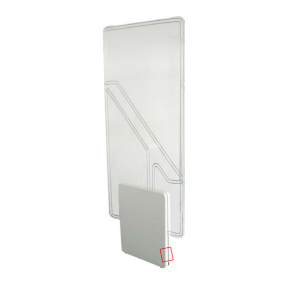
IDENTIFICATION Installation ID ISC.ANT1520/680-A/-B 5.2 Installing the antenna 5.2.1 Dimensions of antenna The overall dimensions of the antenna are shown in Antenna outside dimensions Antenna outside dimensions All dimensions are in mm with general tolerance according to ISO 2768 m (mean). - Page 19 IDENTIFICATION Installation ID ISC.ANT1520/680-A/-B All dimensions are in mm with general tolerance to ISO 2768 m (middle). The size and type of the anchors depends considerably on the strength of the base or floor. The anchors should be capable of withstanding a permissible load of at least 5 kN per anchor for all load directions (e.g.
-
Page 20: Installing The Antenna Base And Antenna Body
IDENTIFICATION Installation ID ISC.ANT1520/680-A/-B 5.2.3 Installing the Antenna Base and Antenna Body The antenna will be mounted on the floor. Please note, the antenna conductors in the middle of the antenna body have to have the same direction (Fig. 7). Afterwards, the antenna has to be aligned the antenna vertically, by using the adjusting screws (Fig. -
Page 21: Typical Antenna Configuration (Gate Antenna With Two Antennas)
The standard configuration of a gate with three-dimensional tag orientation consists of one ID ISC.ANT1520/680-A with reader and multiplexer and one ID ISC.ANT1520/680-B. If a tag moves, at horizontal line, through the gate, it can be read at least once. This ensures high reliability of the antenna system. - Page 22 IDENTIFICATION Installation ID ISC.ANT1520/680-A/-B If multiple gates are arranged with short distances (1-8m) between each other, these will mutually interfere with each other. In this case, the readers for the individual gates have to be synchronized and run in one of the automatic modes.
- Page 23 IDENTIFICATION Installation ID ISC.ANT1520/680-A/-B Transmitted Minimum Distance output power < 0.5 W 0.5 W-1.0 W 1.1 W – 2.0 W > 2 W >= 4 W Table 4: Minimum Distances There should be no interference of the Reader from other electrical devices in the environment.
-
Page 24: Project Notes People Counter (Gpc)
IDENTIFICATION Installation ID ISC.ANT1520/680-A/-B 6.2 Project Notes People Counter (GPC) The radar sensor of the People Counter detect moving objects within the detection area / beam (A1, A2, see Fig. 11) of the radar antenna. The size of the detection area, and hence the sensitivity... - Page 25 IDENTIFICATION Installation ID ISC.ANT1520/680-A/-B Sensitivity Low: Medium: High: Very high: JP1+2 open JP1 closed JP2 closed JP1+2 closed Distance A 180 cm 200 cm 200 – 220 cm 240 - 260 cm Distance B 60–70 cm 80-90 cm 100-110 cm 120 –...
-
Page 26: Gate Configuration And Setup Using Antennas
6.3 Gate Configuration and Setup using Antennas 6.3.1 Required Components To set up the gate you need the following components: Qty. 1 ID ISC.ANT1520/680-A Crystal Gate (Base) (incl. Qty. 1 ID ISC.NET24V-B Power Supply Unit) Qty. 1 ID ISC. ANT1520/680-B Crystal Gate... -
Page 27: Configuration Of A Gate Antenna With Multiplexer
IDENTIFICATION Installation ID ISC.ANT1520/680-A/-B 6.3.2 Configuration of a Gate Antenna with Multiplexer Connect the components as shown in Fig. 12 . Almost, all cable should be mounted already. Normally, the antenna cable from antenna Type B has to be connected to OUT2 at the multiplexer and the 24V DC power supply to X11 of the terminal board. - Page 28 IDENTIFICATION Installation ID ISC.ANT1520/680-A/-B Fig. 13: Terminal board An overview of the terminal board assignment is given in 10. Annex A Note: • A reverse polarity could damage the device or the In-/Outputs. FEIG ELECTRONIC GmbH Page 27 of 82 ID ISC.ANT1520680-A-B User...
- Page 29 IDENTIFICATION Installation ID ISC.ANT1520/680-A/-B Find here the wire connection between antenna Type A and B At a single gate with 2 antennas a connection between X13 GPC-out of the terminal board in Antenna Type A and X13 GPC-out of the terminal board in Antenna Type B must be installed.
- Page 30 IDENTIFICATION Installation ID ISC.ANT1520/680-A/-B The coax cables have fixed lengths and may not be shortened and therefore need to be tied into small loops (see Fig. 16). Tie all cables as far away from the antenna conductor as possible. The cables must never be allowed to contact the antenna conductor.
- Page 31 IDENTIFICATION Installation ID ISC.ANT1520/680-A/-B Fig. 16:Connection of the components in an antenna Type A FEIG ELECTRONIC GmbH Page 30 of 82 ID ISC.ANT1520680-A-B User Manual_M61112-1e-ID-E- 060317.doc...
- Page 32 IDENTIFICATION Installation ID ISC.ANT1520/680-A/-B The cable from antenna type B to the antenna type A should preferably be connected shortly. Unused cable lengths are possible should be tied in antenna B type. Tie all cables as far away from the antenna conductor as possible. The cables must never be allowed to contact the antenna conductor.
-
Page 33: Setting The Multiplexer
IDENTIFICATION Installation ID ISC.ANT1520/680-A/-B 6.3.3 Setting the Multiplexer The jumpers JP11-JP14 should be set (factory setting) as shown. More on setting the ID ISC.ANT.MUX.M4 Multiplexer can be found in the corresponding installation manual (M90700-xde-ID-B). Fig. 18: Jumper positions FEIG ELECTRONIC GmbH Page 32 of 82 ID ISC.ANT1520680-A-B User... -
Page 34: Interface Connections
IDENTIFICATION Installation ID ISC.ANT1520/680-A/-B 6.3.4 Interface Connections 6.3.4.1 LAN / TCP/IP The Reader has an integrated 10 / 100 Base-T network port for an RJ-45. Connection is made on X1 and has an automatic “Crossover Detection” according to the 1000 Base-T Standard. -
Page 35: Reader Configuration With Multiplexer
IDENTIFICATION Installation ID ISC.ANT1520/680-A/-B 6.3.5 Reader Configuration with Multiplexer To tune the antennas, open the ISOStart software and read out the current configuration of the Reader: Step Action Note Start ISO Start Software Select „Detect“ Select „Run without change“ Note:... - Page 36 IDENTIFICATION Installation ID ISC.ANT1520/680-A/-B Step Action Note Select „Expert Mode“ and confirm with OK. Select “Logical View” FEIG ELECTRONIC GmbH Page 35 of 82 ID ISC.ANT1520680-A-B User Manual_M61112-1e-ID-E- 060317.doc...
- Page 37 IDENTIFICATION Installation ID ISC.ANT1520/680-A/-B Afterwards set the operating power, Transponder Parameters and ISO Host Mode: Step Action Note Select “Configuration” Air Interface: “Output -Power” = 8W „Multiplexer Enable“ „1 Input (Single Mode)“ „No of Output Channels „ (e.g. 2) „Antenna Active Time“...
-
Page 38: Tuning The Gate Antenna
IDENTIFICATION Installation ID ISC.ANT1520/680-A/-B Step Action Note Operating Mode: For antenna tuning the reader has to be set to „Host Mode“. Set by clicking on „Apply“. 6.3.6 Tuning the Gate Antenna Before tuning the gate antenna, you must quit the ISOStart software. Then the gate can be tuned... - Page 39 IDENTIFICATION Installation ID ISC.ANT1520/680-A/-B Step Action Note The tuning status is displayed after each tuning pass. After successful tuning both antennas are shown in green. If this does not succeed on the first try, start the process again by clicking on „Start Tuning“...
-
Page 40: Testing The Gate Antenna
IDENTIFICATION Installation ID ISC.ANT1520/680-A/-B 6.4 Testing the Gate Antenna After tuning the gate antenna, you can check for proper function using a reader, the ISOStart service software and a Transponder. Here the Noise Level and performance of the gate are tested. - Page 41 IDENTIFICATION Installation ID ISC.ANT1520/680-A/-B Step Action Note Activate antenna 2 with command: „Function Unit Commands - Multiplexer“ Parameter: „Channel Select“ „Cascade Level = 1“ „Output Channel of Input 1 = 2“ Confirm with “Send” Repeat Step 3 to 5 for...
-
Page 42: Reading A Serial Number
IDENTIFICATION Installation ID ISC.ANT1520/680-A/-B 6.4.2 Reading a Serial Number Step Action Note Attach a tag to an antenna Use adhesive tape, for example Here to antenna at multi- plexer output 1 Activate antenna 1 with command: „Function Unit Commands - Multiplexer“... -
Page 43: Testing The Performance
IDENTIFICATION Installation ID ISC.ANT1520/680-A/-B 6.4.3 Testing the performance For testing the performance you must switch the reader to one of the Automatic Modes. A read transponder will be displayed by a blue LED on the reader, the Alarm LED light of the antenna and the Alarm buzzer. - Page 44 IDENTIFICATION Installation ID ISC.ANT1520/680-A/-B If one or more „holes“ are detected, check the noise values on the Reader (see 6.4.1 Checking the Noise Level). The following may result in faulty readings: • Antenna improperly installed (orientation, antenna distance, check cabling) •...
-
Page 45: Setting The Alarm Indicators (Alarm Buzzer And Alarm Led´s)
IDENTIFICATION Installation ID ISC.ANT1520/680-A/-B 6.5 Setting the Alarm indicators (Alarm Buzzer and Alarm LED´s) 6.5.1 Setting the Buzzer The solution provided here presumes that the alarm indicator (buzzer) is switched through the digital output 2 /X2 on the ID ISC.LRM2500-B reader. The pulse duration can be set (CFG2 / OUT2) between 100 ms and 65535 s by adjusting the Reader configuration. -
Page 46: Setting The Led´s
IDENTIFICATION Installation ID ISC.ANT1520/680-A/-B 6.5.2 Setting the LED´s The alarm LED´s will be switched by a command of the reader over the RS485 Bus. Due to that reason the terminal boards of all used antennas have to be connected 1:1 in parallel together. -
Page 47: Reader Setting For Alarm Indicators
IDENTIFICATION Installation ID ISC.ANT1520/680-A/-B 6.5.3 Reader Setting for Alarm Indicators The ISOStart software can be used to set the Reader configuration so that the output 2 X6-1/-2 opens or closes or the LED´s get a command when a Transponder is read. - Page 48 IDENTIFICATION Installation ID ISC.ANT1520/680-A/-B Assign LED Bus Address 11 to antenna 1. LED Bus Address 12 to antenna 2..and so on. „True“ means: LED with Bus Address 11, 12, ... 17 will be active if the reader read a...
-
Page 49: Programming A Transponder With The Afi Byte
IDENTIFICATION Installation ID ISC.ANT1520/680-A/-B 6.5.4 Programming a Transponder with the AFI Byte If the Transponders will remain on the object when leaving the storage location, they must first be disabled. This is generally done by writing to a particular area of the Transponder. - Page 50 IDENTIFICATION Installation ID ISC.ANT1520/680-A/-B To verify, read AFI byte by using the command [0x2B] Get System Information FEIG ELECTRONIC GmbH Page 49 of 82 ID ISC.ANT1520680-A-B User Manual_M61112-1e-ID-E- 060317.doc...
-
Page 51: Functions Of The Lcd-Display
IDENTIFICATION Installation ID ISC.ANT1520/680-A/-B 6.6 Functions of the LCD-Display Only in the Automatic Modes (Scan, Notification or Buffered read Mode) the Display will work as described. After power up the antenna type A or the command “System Reset” the Display will... - Page 52 IDENTIFICATION Installation ID ISC.ANT1520/680-A/-B Step Description Display Then the counter values for IN and OUT of all connected GPC. After that the display will change between ALL and IN /OUT values The Counter values in the display will be updated...
- Page 53 IDENTIFICATION Installation ID ISC.ANT1520/680-A/-B Step Description Display If an error occurs the Error Code will be shown together with the ALL values. The meaning of the Error Code will be shown in table 10 below. Error Code Error Flag RF-HW |Z| <...
-
Page 54: Activating The Automatic Mode
IDENTIFICATION Installation ID ISC.ANT1520/680-A/-B 6.7 Activating the Automatic Mode The gate has to be used in one of the Automatic Modes (Buffered Read, Notification or Scan Mode) to get a maximum performance. Otherwise the reading performance will be significantly reduced. -
Page 55: Installation Id Isc.ant.gpc-E2
IDENTIFICATION Installation ID ISC.ANT1520/680-A/-B 6.8 Installation ID ISC.ANT.GPC-E2 Content of the ID ISC.ANT.GPC-E2 1. 1 piece Radar connection cable 2. 1 piece Radar module 3. 2 piece spilt rivet 3,0mm 4. 1 piece cable-clip Step Action Note Attention !! Note: Do not touch the an-... - Page 56 IDENTIFICATION Installation ID ISC.ANT1520/680-A/-B Plug Radar connection cable into X12 Sen 2 and fix the cable with the cable clip. Install Radar module with the two split rivets See picture The sensitivity of the radar To check/set the sensitivity see also 7.2.2 Configuration and...
-
Page 57: Installation Of The Gate People Counter Id Isc.ant.gpc In Antenna Type B
IDENTIFICATION Installation ID ISC.ANT1520/680-A/-B Installation of the Gate People Counter ID ISC.ANT.GPC in antenna Type B 7.1 Installation and Connections Contents of the 1 piece connection cable People Counter –Terminal board ID ISC.ANT.GPC 1 piece Radar connection cable 1 piece LED connection cable... - Page 58 IDENTIFICATION Installation ID ISC.ANT1520/680-A/-B Action Step Note Disconnect LED connection cable at the terminal board and cut the cable tie in the antenna foot. Disconnect LED connection cable at LED controller. FEIG ELECTRONIC GmbH Page 57 of 82 ID ISC.ANT1520680-A-B User Manual_M61112-1e-ID-E- 060317.doc...
- Page 59 IDENTIFICATION Installation ID ISC.ANT1520/680-A/-B Remove the cable clip be- side the LED controller. FEIG ELECTRONIC GmbH Page 58 of 82 ID ISC.ANT1520680-A-B User Manual_M61112-1e-ID-E- 060317.doc...
- Page 60 IDENTIFICATION Installation ID ISC.ANT1520/680-A/-B Remove the 2 other cable clips by pulling them out with the cable. Install People Counter Board into antenna with screws for plastic Plug GPC connection cable onto X1 at GPC and X5 GPC-in at terminal board and fix it with two cable clips and the cable tie.
- Page 61 IDENTIFICATION Installation ID ISC.ANT1520/680-A/-B Attention !! Note: Do not touch the an- tenna surface of the Radar module to avoid damaging the electronic components and soiling. Connect radar connection cable with X1 of Radar module. FEIG ELECTRONIC GmbH Page 60 of 82 ID ISC.ANT1520680-A-B User...
- Page 62 IDENTIFICATION Installation ID ISC.ANT1520/680-A/-B Plug Radar connection cable onto X11 Sen 1 at GPC and fix the cable with the cable clip. Install Radar module with split rivet. Use installation hole that radar module surface faces between the antennas. The sensitivity of the radar To check/set the sensitivity see also 7.2.2 Configuration and...
- Page 63 IDENTIFICATION Installation ID ISC.ANT1520/680-A/-B Connect LED cable with X1 of LED controller and fix it with the cable clips. Connect the LED cable with X3 of GPC Close antenna with antenna cover with display window After the installation you have to stick the adhesive label of the GPC below the type plate of the antenna.
-
Page 64: Configuration And Test
IDENTIFICATION Installation ID ISC.ANT1520/680-A/-B 7.2 Configuration and Test To activate the People Counters the following settings has to be done. Set additional the Jumpers JP10 and J11 of Reader ID ISC.LRM2500-B to configure the RS485 interface. (see also manual M01111-xde-ID-B , page 54 and 55). The Termination has to be acti- vated via software in the reader configuration. - Page 65 IDENTIFICATION Installation ID ISC.ANT1520/680-A/-B The number of detected GPC and it´s firmware version will also be shown at the LCD-Display after a power up or the command “System Reset” in one of the Automatic Modes. FEIG ELECTRONIC GmbH Page 64 of 82 ID ISC.ANT1520680-A-B User...
-
Page 66: Configuration And Test In Iso-Host Or Buffered Read
IDENTIFICATION Installation ID ISC.ANT1520/680-A/-B 7.2.2 Configuration and Test in ISO-Host or Buffered Read Step Action Note Select „Configuration“ Host Interface Set RS 485 to “False” and „Enable Termination Resistors“ The RS232/485 Settings should be set to: Busaddress=0, Baudrate=38400 baud, Parity = even ,... - Page 67 IDENTIFICATION Installation ID ISC.ANT1520/680-A/-B „True“ means: LED with Bus Address 11, 12, ... 17 will be active if the reader read a valid transponder on the corresponding antenna Set by clicking on „Apply“. The sensitivity of the connected radar modules...
- Page 68 IDENTIFICATION Installation ID ISC.ANT1520/680-A/-B Confirm with „Send“ Number of Devices should be 1 Select Command „Set People Counter Values“ Confirm with „Send“ Select Command „Get People Counter Values“ Confirm with „Send“ All counter values should be 0 Walk through the gate from both directions.
- Page 69 IDENTIFICATION Installation ID ISC.ANT1520/680-A/-B Confirm with „Send“ Counter values will be displayed. In ISO-Host and Buffered Read the People Counter has to be polled by the Host Application to get the data. FEIG ELECTRONIC GmbH Page 68 of 82 ID ISC.ANT1520680-A-B User Manual_M61112-1e-ID-E- 060317.doc...
-
Page 70: Configuration And Test In Notification Mode
IDENTIFICATION Installation ID ISC.ANT1520/680-A/-B In Notification Mode the Reader sends the People Counter Data automatically to the Host. 7.2.3 Configuration and Test in Notification Mode The following configuration hast to be done: Step Action Note Select „Configuration“ Peripheral Devices Mode Set “Enable Notify Counter”... - Page 71 IDENTIFICATION Installation ID ISC.ANT1520/680-A/-B A Test could be done with the People Counter Sample. Therefore you will have to set both ports have the same address, at the TCP- Settings. FEIG ELECTRONIC GmbH Page 70 of 82 ID ISC.ANT1520680-A-B User Manual_M61112-1e-ID-E- 060317.doc...
-
Page 72: Using The Trigger Function Of The Gate People Counter
IDENTIFICATION Installation ID ISC.ANT1520/680-A/-B 7.2.4 Using the trigger function of the Gate People Counter The trigger function could only be used in one of the Automatic Modes. The trigger function works bidirectional, but a 100% safe reading of transponder is only possible from one direction. - Page 73 IDENTIFICATION Installation ID ISC.ANT1520/680-A/-B Step Action Note Select „Configuration“ Operating Mode Select -Buffered Read Mode -Notification Mode Confirm with „Apply“ Operating Mode -Trigger enable -Source Input No 2-Trigger TriggerUse set to - Start Trigger - Hold Time e.g. 20x100ms =2sec.
-
Page 74: Using The Direction Detection Of Transponder With The People Counter
IDENTIFICATION Installation ID ISC.ANT1520/680-A/-B 7.2.5 Using the direction detection of transponder with the People Counter In combination with the People Counter a direction detection of the transponders could be per- formed in that way, that only transponder will cause an alarm which move in the configured direc- tion through the gate. -
Page 75: Configure The Reader In Accordance With National Rf Regulations
42 dBµA/m at 10 m distance. RF approval (at a maximum field strength of 84 dBµV/m at 30 m) for the ID ISC.ANT1520/680 antenna with ID ISC.LRM2500 Reader has been granted in accordance with FCC Part 15 for the USA and the RSS-210 for Canada RF approval in accordance with EN 300 330 is still possible in all 46 CEPT countries. - Page 76 IDENTIFICATION Installation ID ISC.ANT1520/680-A/-B The reader needs to be configured as follows depending on the installation location: Parameter USA / Canada / Europe Air Interface RF-Power: maximum 8 W RF Modulation: Transponder RF Modulation / ISO-MODE / RF Data coding ISO-MODE:...
-
Page 77: Technical Data
IDENTIFICATION Installation ID ISC.ANT1520/680-A/-B Technical Data 9.1 Antenna ID ISC.ANT1520/680 Type A and B Mechanical Data • Housing UV stabilized ABS and Acrylic • Dimensions ( W x H x D ) 680 mm x 1798 mm x 76 mm ± ± ± ± 3 mm –... - Page 78 IDENTIFICATION Installation ID ISC.ANT1520/680-A/-B • Operating Frequency 13,56 MHz • Maximum transmitting power per antenna • Permissible overall transmitting power per antenna gate 8.0 W – EU-territory (per EN 300 330) 8.0 W – USA (per. FCC Part 15) 8.0 W - Canada (per.
- Page 79 Product testing * Persistent deformation after load release approx. 3 cm. ** Qty. 2 ID ISC.ANT1520/680-A/-B antennas, antenna spacing (antenna center), same flow direc- tion, Tag 46 mm x 75 mm ISO15693, sensitivity / minimum field strength H =60 / 40 mA/m rms, transmitting power 8 W, tag orientation parallel to antenna for horizontal movement through the antenna.
-
Page 80: People Counter Id Isc.ant.gpc And Id Isc.ant.gpc-E2
IDENTIFICATION Installation ID ISC.ANT1520/680-A/-B 9.2 People Counter ID ISC.ANT.GPC and ID ISC.ANT.GPC-E2 Mechanical Data • Housing Printed Boards • Board Dimensions ( B x H x T ) 100 mm x 40 mm x 16 mm ± ± ± ± 1 mm –... - Page 81 IDENTIFICATION Installation ID ISC.ANT1520/680-A/-B FEIG ELECTRONIC GmbH Page 80 of 82 ID ISC.ANT1520680-A-B User Manual_M61112-1e-ID-E- 060317.doc...
-
Page 82: Power Supply Id Isc.net24V-B
IDENTIFICATION Installation ID ISC.ANT1520/680-A/-B 9.3 Power Supply ID ISC.NET24V-B Will be included in the packaging of the antenna ID ISC.ANT1520/680 Type HPDA Mechanical Data • Type Desktop power supply with IEC socket ac- cording IEC60320-C13, 3-pin • Housing Plastic •... -
Page 83: Approvals
Equipment Classification according to ETSI EN 300 330 and ETSI EN 301 489: Class 2 The technical data of the ID ISC.LRM2500-B Reader built into the ID ISC.ANT1520/680-A an- tenna can be found in the Installation Manual which is included with the device. -
Page 84: Usa (Fcc) And Canada (Ic)
Further information and technical data of the ID ISC.LRM2500-B Reader built into the ID ISC.ANT1520/680 antenna can be found in the Installation Manual of the reader. FEIG ELECTRONIC GmbH Page 83 of 83 ID ISC.ANT1520680-A-B User... -
Page 85: People Counter Id Isc.ant.gpc
IDENTIFICATION Installation ID ISC.ANT1520/680-A/-B 9.4.2.2 People Counter ID ISC.ANT.GPC FCC ID: UXS-IPS154US 6633A-GPC This device complies with Part 15 of the FCC Rules and with Notice for USA and Canada RSS-210 of Industry Canada. Operation is subject to the following two conditions. -
Page 86: Usa And Canada (Ul)
IDENTIFICATION Installation ID ISC.ANT1520/680-A/-B 9.4.3 USA and Canada (UL) The following picture indicates the label position: The following picture indicates the label position: FEIG ELECTRONIC GmbH Page 85 of 85 ID ISC.ANT1520680-A-B User Manual_M61112-1e-ID-E- 060317.doc... -
Page 87: Annex A
IDENTIFICATION Installation ID ISC.ANT1520/680-A/-B 10 Annex A 10.1 Terminal assignment “Terminal Board” Terminal Acronym Description X1 / LR 24V DC Reader X1 / Pin 1 +24 V DC Reader X1 / Pin 2 GND Reader X2 / LR I/O 24V DC Input/Output , RS485... -
Page 88: Internal Wiring
IDENTIFICATION Installation ID ISC.ANT1520/680-A/-B X13 / Pin 3 TRG Trigger People Counter X13 / Pin 4 RS485 A- X13 / Pin 5 RS485 B+ Table 11: Pin-Configuration X1-X13 Terminal Board 10.2 Internal wiring Terminal Acronym Description X1 / LR 24V DC Reader... - Page 89 IDENTIFICATION Installation ID ISC.ANT1520/680-A/-B FEIG ELECTRONIC GmbH Page 88 of 88 ID ISC.ANT1520680-A-B User Manual_M61112-1e-ID-E- 060317.doc...
Need help?
Do you have a question about the ID ISC.ANT1520/680 and is the answer not in the manual?
Questions and answers