Table of Contents
Advertisement
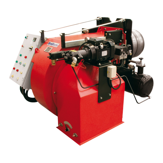
HEAVY OIL BURNERS
OILFLAM 700.1 PR
OILFLAM 800.1 PR
OILFLAM 1000.1 PR
OILFLAM 1200.1 PR
Technical data
Operating instructions
Electric diagrams
Spare parts list
www.ecoflam-burners.com
OILFLAM 700.1 PR TC 230-400-50
OILFLAM 800.1 PR TC 230-400-50
OILFLAM 1000.1 PR TC 230-400-50
OILFLAM 1200.1 PR TC 230-400-50
EN
3142127
Advertisement
Table of Contents


Need help?
Do you have a question about the OILFLAM 700.1 PR and is the answer not in the manual?
Questions and answers