Oriental motor OPX-2A Operating Manual
Data setter for the blv series
Hide thumbs
Also See for OPX-2A:
- Operating manual (44 pages) ,
- Quick start manual (8 pages) ,
- User manual (212 pages)
Table of Contents
Advertisement
HP-5049-3
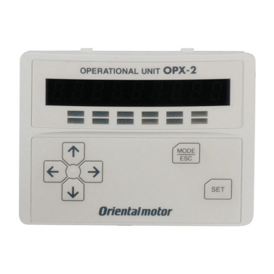
Data setter
OPX-2A
For the BLV Series
OPERATING MANUAL
Thank you for purchasing an Oriental Motor product.
This Operating Manual describes product handling procedures and safety precautions.
• Please read it thoroughly to ensure safe operation.
• Always keep the manual where it is readily available.
Advertisement
Table of Contents

Related Manuals for Oriental motor OPX-2A


Summary of Contents for Oriental motor OPX-2A
- Page 1 OPX-2A For the BLV Series OPERATING MANUAL Thank you for purchasing an Oriental Motor product. This Operating Manual describes product handling procedures and safety precautions. • Please read it thoroughly to ensure safe operation. • Always keep the manual where it is readily available.
-
Page 2: Table Of Contents
8 Parameter mode ....... 20 How to read the LED indicators ....6 Types of operation modes ....... 6 Parameter ID ......... 20 Basic operations of the OPX-2A ....7 Setting example ........30 Edit lock function ........8 9 Test mode .......... 32 Rewriting the driver’s non-volatile... -
Page 3: Safety Precautions
Also read the "Safety precautions" sections in the USER MANUAL that came with the product you are combining with the OPX-2A. Handling the product without observing the instructions that accompany a "Warning" symbol may result in serious injury or death. -
Page 4: Introduction
„ Overview of the product „ The OPX-2A is a data setter that lets you set operation data and parameters, perform monitoring, etc. Use the OPX-2A properly and safely after thoroughly reading the "BLV Series USER MANUAL" and understanding the basic operating procedures and other details. -
Page 5: Preparation
Preparation 3 Preparation This chapter explains the items you should know before using the OPX-2A. 3.1 Checking the product Verify that the items listed below are included. Report any missing or damaged items to the branch or sales office from which you purchased the product. -
Page 6: How To Read The Display
Lit while the edit lock function is enabled Lit while the motor is operating Not used 3.5 Types of operation modes The OPX-2A has multiple operation modes. The Monitor mode operation mode will change every time the (MON) key is pressed. -
Page 7: Basic Operations Of The Opx-2A
Use the six keys to set data and operate the motor. „ Operation flow „ The OPX-2A is operated according to the flow shown below. Level 1: Top screen in each mode Level 2: Item selection screen Level 3 Use the... -
Page 8: Edit Lock Function
Preparation „ How to input values „ As an example, how to change the rotation speed from "80" r/min to "1000" r/min is explained. Basic operations • Use the keys to increase/decrease the value or change the sign. Use the keys to move to the digit you want to edit. -
Page 9: Rewriting The Driver's Non-Volatile Memory
100,000 times. The non-volatile memory will be rewritten after one of the following operations is performed: • Edit any operation data or parameter • Download data from the OPX-2A to the driver • Initialize driver operation data and parameters −9−... -
Page 10: Installation And Connection Of The Opx-2A
• 1000 m (3300 ft.) or less above sea level 4.2 Installation method Using a metal plate of 1 to 3 mm (0.04 to 0.12 in.) in thickness, insert the OPX-2A into the mounting hole from the front side and securely attach it. -
Page 11: Connecting To The Driver
Once stored in the driver, the data will not be cleared even after the OPX-2A is disconnected from the driver. • Turning on the power to the driver will also turn on the power to the OPX-2A. Turning off the driver power will turn off the OPX-2A power. -
Page 12: Screen Transitions
Screen transitions 5 Screen transitions Top screen Monitor mode Operation speed Present warning Warning record 1 (latest) Conveyor transfer speed Warning record 10 (oldest) Load factor Clear warning records Processing is Operation data in progress number (blinking display) I/O monitor Input monitor Present alarm Operation speed... - Page 13 Screen transitions Note • The following limitations are present while the edit lock function is enabled. · Data mode, parameter mode: These are displayed in the screen but cannot be operated. · Clearing of the alarm and warning records, copy mode: These are not displayed in the screen. •...
- Page 14 Screen transitions Parameter mode Test mode Data mode Parameter selection I/O test (Example: speed increasing ratio) Input test Parameter setting Output test Output test Writing of data is in progress (blinking display) Voltage test of external speed setting Enter the parameter ID and press key, then move to the setting screen for each parameter.
- Page 15 Screen transitions Copy mode Monitor mode Download Initialization Data bank selection 0 Initialize operation data Processing is Processing is in progress in progress (blinking display) (blinking display) Data bank selection 3 Initialize parameters Processing is Processing is in progress in progress (blinking display) (blinking display) Upload...
-
Page 16: Monitor Mode
Monitor mode 6 Monitor mode 6.1 Overview of the monitor mode • Monitoring the operating status You can monitor the motor operation speed, conveyor transfer speed, load factor and operation data number corresponding to the current operation. • Checking alarms/warnings, clearing alarm/warning records, and resetting alarms •... - Page 17 • When operations are limited by the edit lock function, the alarm records cannot be cleared. • Some alarms cannot be reset by the OPX-2A. For details, refer to the table below. To reset these alarms, you must cycle the driver power.
- Page 18 Monitor mode „ I/O monitor „ You can check the ON/OFF status of each I/O signal of the driver. Each digit on the 7-segment LED display corresponds to a signal. If the signal is ON, the corresponding digit is lit. If the signal is OFF, the digit is unlit. •...
-
Page 19: Data Mode
*1 The initial value is motor starting torque. The rated torque being 100%. *2 This is the case when being set digitally by the OPX-2A. If any analog setting mode (internal potentiometer, external potentiometer or external DC voltage) is selected, the time over which to reach the rated rotation speed (3000 r/min) is indicated. -
Page 20: Parameter Mode
1 second. If this error display appears, input a different value that falls within the setting range. 8.1 Parameter ID There is an unique ID in each parameter. With the OPX-2A, set the parameter selecting the ID. „ Timing for the setting value to become effective „... - Page 21 One is the time needed to reach the target speed from the current speed when using digital setting (using the OPX-2A). Another is the time needed to reach the rated rotation speed (3000 r/min) when using analog setting (using the internal potentiometer, external potentiometer or external DC voltage).
- Page 22 Parameter mode Setting Initial Name Setting range Effective* unit value Torque limiting value No.0 Torque limiting value No.1 Torque limiting value No.2 Torque limiting value No.3 0 to 200% Torque limiting value No.4 Torque limiting value No.5 Torque limiting value No.6 Torque limiting value No.7 * Indicates the timing for the data to become effective A: Effective immediately...
- Page 23 Parameter mode Setting Initial Name Description Setting range Effective* unit value Set the band within which the rotation Rotation speed 2215 speed of the motor is deemed to have 0 to 400 r/min attainment band reached the set value. JOG operation Set the rotation speed of JOG 0 r/min, and 80 speed...
- Page 24 Parameter mode • Display the conveyor transfer speed To display the conveyor transfer speed on OPX-2A, set the conveyor speed reduction ratio by using the formula below: Gearhead gear ratio Conveyor speed reduction ratio = Pulley diameter [m] × π...
- Page 25 Parameter mode • Operation data setting using analog input signal selection Setting method of operation data can be changed using the analog input signal selection parameter [ID: 2161]. See a combination of the mode No. and analog setting/digital setting as shown below. Others except the following combination are not available to set.
- Page 26 * Indicates the timing for the data to become effective A: Effective immediately, C: Effective after turning the power ON again „ Parameters [Data setter] „ Set the display method of the data setter OPX-2A. Check the display description with the monitor mode. Initial Name Description...
- Page 27 The motor stops when the external error signal is input (normally closed). ALARM-RESET Resets the alarm. Disable the operation with the OPX-2A and use it as a display. Select operation data by a combination of ON/OFF statuses of the M0 to M2 inputs. ALARM-OUT1 This signal is output when an alarm generates (normally closed).
- Page 28 Parameter mode „ Parameters [RS-485 communication] „ Parameters for RS-485 communication can be set. Name Setting range Initial value Effective*2 0: Not monitored 2304 Communication timeout*1 0 to 10000 ms 2305 Communication error alarm*1 1 to 10 times 0: None 2563 Communication parity*1 1: Even number...
- Page 29 Parameter mode Name Setting range Initial value Effective*1 NET-OUT0 output function 2240 48: M0_R selection NET-OUT1 output function 2241 49: M1_R selection NET-OUT2 output function 2242 50: M2_R selection NET-OUT3 output function 1: FWD_R 2243 selection (START/STOP_R) NET-OUT4 output function 2: REV_R 0: Not used 2244...
-
Page 30: Setting Example
Parameter mode 8.2 Setting example Pressing the key in the parameter item screen enables parameter setting. How a parameter is set is explained below. Example: Set the speed reduction ratio [ID: 2085] to “50.0” Top screen of the parameter mode Use the key to select the parameter mode. - Page 31 Parameter mode Note • If the value you have input is outside the setting range, “Error” will be displayed for 1 second. If this error display appears, input a different value that falls within the setting range. • If a nonexistent parameter ID is entered, “id-Error” will be displayed for 1 second. Check the ID and enter the correct one.
-
Page 32: Test Mode
• I/O test You can check the ON/OFF status of each input signal of the driver, or switch the ON/OFF status of each output signal on the OPX-2A. Perform I/O test to check the connection condition between the driver and host controller. -
Page 33: Jog Operation
9.3 JOG operation You can operate the motor using the keys on the OPX-2A. The operation speed corresponds to the value set in the JOG operation speed parameter [ID: 323] and the torque corresponds to the value set in the JOG operation torque parameter [ID: 2081]. -
Page 34: Copy Mode
Since NV memory is used as the data memory element, stored data will be retained even after the power is turned off. In the copy mode, you can download data saved in the OPX-2A to the driver. You can also upload data saved in the driver to the OPX-2A. -
Page 35: Downloading To The Driver
OPX-2A. Perform download again. If the same error occurs, the data An error occurred while data was saved in the OPX-2A may be being downloaded. damaged. Upload the applicable data to set the OPX-2A data again. The specified data bank number Check the data bank number. -
Page 36: Verifying Data
OPX-2A. Perform verification again. If the same error occurs, the data An error occurred while data was saved in the OPX-2A may be being verified. damaged. Upload the applicable data to set the OPX-2A data again. The specified data bank number Check the data bank number. - Page 37 Copy mode −37−...
- Page 38 −38−...
- Page 39 −39−...
- Page 40 If a new copy is required to replace an original manual that has been damaged or lost, please contact your nearest Oriental Motor branch or sales office. • Oriental Motor shall not be liable whatsoever for any problems relating to industrial property rights arising from use of any information, circuit, equipment or device provided or referenced in this manual.
Need help?
Do you have a question about the OPX-2A and is the answer not in the manual?
Questions and answers