Table of Contents
Advertisement
®
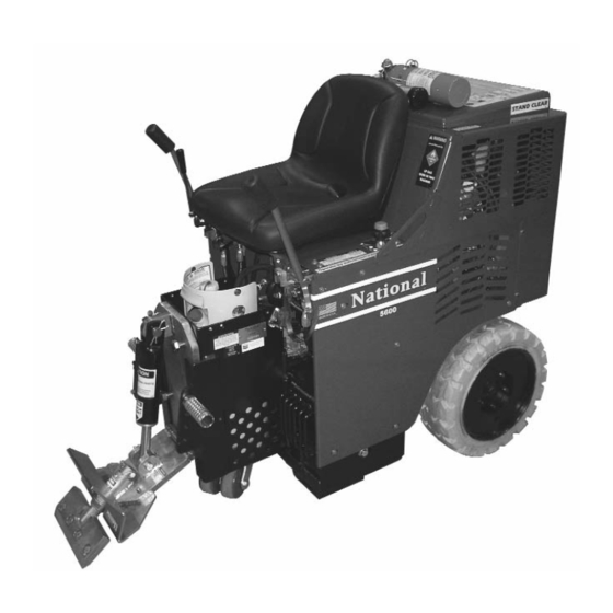
#5600 PANTHER
PROPANE POWERED
FLOOR PREP SYSTEM
INSTRUCTION
MANUAL
Read Manual Before Operating Machine
National
Flooring Equipment, Inc.
9250 X
A
N
• M
, MN 55445 • U.S.A.
YLON
VENUE
ORTH
INNEAPOLIS
800-245-0267 • 763-535-8206 • F
763-535-8255 • F
800-648-7124
AX
AX
402565 Rev A
W
S
: www.nationalequipment.com • E-M
: info@nationalequipment.com
EB
ITE
AIL
Advertisement
Table of Contents
Troubleshooting

Related Manuals for National 5600


Summary of Contents for National 5600
- Page 1 ® #5600 PANTHER PROPANE POWERED FLOOR PREP SYSTEM INSTRUCTION MANUAL Read Manual Before Operating Machine National Flooring Equipment, Inc. 9250 X • M , MN 55445 • U.S.A. YLON VENUE ORTH INNEAPOLIS 800-245-0267 • 763-535-8206 • F 763-535-8255 • F...
-
Page 2: Table Of Contents
TABLE OF CONTENTS Table of Contents ....................2-5 Hydraulic Safe Operation ..................6-7 A. Maintaining A Safe Work Environment ..............6 B. Pressure......................6-7 C. Flammability ......................7 D. Hydraulic Fluid......................7 Rules for Safe Operation..................8-10 A. General Rules ....................8-9 B. Characteristics of a Defensive Operator ............10 Safety Instructions/ Precautions ................11-12 Battery Safe Operation ....................13 A. -
Page 3: Table Of Contents
TABLE OF CONTENTS Loading/Unloading ....................24-25 A. Dock Heights ....................24 B. Power-Gate ......................24 C. Ramps ......................24 D. Forklift Cups ....................25 E. Winches ......................25 F. Transporting ....................25 G. Wheel Chocks ....................25 Center of Gravity ......................26 Job Site Movement ....................27-28 A. Taping Wheels....................27 B. - Page 4 TABLE OF CONTENTS E. Double Stick Carpet Set-Up ................33 F. VCT Tile Set-Up ....................33 G. Rubber Tile Set-Up ....................33 H. Re-Scraping Set-Up ..................34 I. Thin Coating Set-Up ..................34 J. Working Over Concrete..................34 K. Working Over Wood ..................34 L. Working Over Soft Sub-Floor ................34 M.
- Page 5 TABLE OF CONTENTS Complete Parts List ....................48-52 Part Numbers and Diagrams ................53-66 A. External Parts ......................53 B. External Parts ....................54 C. Beeper & Hood Parts ..................55 D. Gear Pump Parts....................56 E. Wheel Parts......................57 F. Control Lever Parts ..................58 G. Single Spool & Hose Parts ................59 H.
-
Page 6: Hydraulic Safe Operation
HYDRAULIC SAFE OPERATION MAINTAINING A SAFE WORK ENVIRONMENT Establishing a safe working environment in and around your hydraulic equipment is just common sense. The easiest and most effective way to avoid problems is to make sure associates understand their equipment, know how to operate it safely and recognize the danger it represents if handled carelessly. A few things you must be aware of include: 1. -
Page 7: Flammability
HYDRAULIC SAFE OPERATION PRESSURE (continued) 3. If the coupling was misaligned during installation, threads may have been damaged. Replace and carefully install. 4. Over torquing of a threaded connection can stretch and damage threads and mating seat angles. Over torquing can also damage the staking area of the nut. Under torquing does not allow proper sealing. -
Page 8: Rules For Safe Operation
Extra copies of the manual and video are available. In cases where personnel have an insufficient knowledge of the English language, proper training must be obtained before using the 5600 machine. 1. KNOW YOUR EQUIPMENT: Read this manual and view instruction video carefully to learn equipment applications and limitations as well as potential hazards associated with this type of equipment. - Page 9 Remove blade or keep blade lowered to the floor (disarm machine). 24. MAINTAIN LABELS AND NAME PLATES: These carry important information. If unreadable or missing, contact National for a free replacement. 25. MACHINE IS HEAVY, DO NOT DROP: Counter weights are heavy. Take caution when removing or reassembling.
-
Page 10: Characteristics Of A Defensive Operator
USE CARBON MONOXIDE DETECTOR WHEN OPERATING MACHINE Included with the 5600 are a 75007 Lapel CO Monitor and a 75008 Clip. It is recommended that the operator and anyone in the working vicinity wear the detector. Failure to do so could cause bodily injury and/or death. -
Page 11: Safety Instructions/ Precautions
• Wear gloves when changing blades. Always shut machine off when changing blades. The 5600 Propane Ride-On should be inspected for damage and defects at least once during every working shift. Starting and stopping procedures must be followed in accordance with the Operating Instructions. -
Page 12: Safety Instructions/ Precautions
The 5600 Propane Ride-On has been equipped with a safety switch under the seat, which requires the operator to be seated before the 5600 can be operated. Do not attempt the start-up procedure with out being seated on the machine. -
Page 13: Battery Safe Operation
BATTERY SAFE OPERATION CAUTION - PRECAUTIONS: a) Contact with electrolytic acid can cause skin irritation and damage clothing. Wear a protective apron, gloves and goggles when working with batteries. Have plenty of fresh water and soap nearby in case battery acid contacts your skin, clothing, or eyes. b) Remove personal metal items such as bracelets, rings, necklaces, and watches when working with batteries. -
Page 14: Motor Safe Operation
MOTOR SAFE OPERATION CAUTION - PRECAUTIONS: Before servicing, allow engine to cool down. Failure to do so could cause bodily injury. CHECK FLUID LEVELS Check oil & coolant levels before operating. CHECK FOR LEAKS Inspect propane gas line for leaks. Page 14... -
Page 15: Troubleshooting
Tighten hose fitting. Replace hose or fitting if necessary 5. The machine has no power a. Check valve adjustment a & b. Contact National with the engine running b. Check hoses for leaks Service Center immediately at 3500 rpm. -
Page 16: Troubleshooting
TROUBLESHOOTING Trouble Possible Cause Remedy 8. Excessive amount of oil a. Outside oil spilled on a. Clean machine thoroughly on chassis chassis and see if oil returns b. Loose hose connections b. Check for loose hoses c. Loose tank fittings c. -
Page 17: Features/Specifications
Rear Weight: 83 lbs. Gross Weight: 1663 Trailer Hitch Speed: Up to 150 feet per minute MOTOR INFORMATION (#5600) WARNING: Trailer hitch is only intended to move small trailers on the job site. RPM: 2950 Volts: 12 Volt System Amps-Full Load:... -
Page 18: Vibration/Sound Data
FEATURES/SPECIFICATIONS VIBRATION/SOUND DATA VIBRATION DATA: Axis Stationary Moving >0.1 Vector >0.1 Whole Body Vibration Levels in m/s^2 Axis Left Right Vector Sum Hand/Arm Vibration Levels in m/s^2 SOUND DATA: Stationary 77.0 Moving 73.0 Operator Sound Level dBA ref. 20 Pa Emissions meets OSHA stantdards Page 18... -
Page 19: Operating Controls
OPERATING CONTROLS START UP PROCEDURE POWER /Key Start (Figure A) 1. Open propane tank valve by turning knob CCW until fully open. 2. Operator must be seated in seat. The machine will not start unless the operator is seated. 3. Insure that hydraulic levers are “centered”. 4. -
Page 20: Hydraulic Levers
OPERATING CONTROLS HYDRAULIC LEVERS (CONTINUED) • Move levers slowly. • Both levers forward move the machine forward. • Both levers backward move the machine backward. • The left lever forward and the right lever backward turn the machine quickly to the right. •... -
Page 21: Shut-Down Mode
F MACHINE IS NOT RUNNING BUT THE KEY IS IN THE IGNITION AND IN ON POSITION HOUR METER WILL CONTINUE TO RUN SHUT DOWN MODE (SHUT DOWN PROCEDURE/ TURNED OFF) Definition: State or condition of the 5600 Propane Ride-On that minimizes the danger of mechanical, electrical, pneumatic or hydraulic hazards. 5600 P UTTING THE ROPANE N IN •... -
Page 22: Changing Propane Tank
ONOXIDE ETECTOR Included with the 5600 are a 75007 Lapel CO Monitor and a 75008 Clip. It is recommended that the operator and anyone in the working vicinity wear the detector. Failure to do so could cause bodily injury and/or death. The use of detectors helps to verify if work area is safe from Carbon Monoxide poisoning. -
Page 23: Operational Tips
OPERATIONAL TIPS CASTER Keep clean and free of debris, make sure it can move freely. Clean as needed. Inspect before each use. Grease once a month. Moving a "weighted" machine only on the front caster and not on the cutting head or the Front Wheel Assembly can seem to make the machine turn sluggish. -
Page 24: Loading/Unloading
LOADING/UNLOADING • Always remove blade and cutting head when machine is being moved or transported • Cutting head and slide plate can be removed to make the machine more compact. • NEVER leave machine unattended on an incline. • Removing added weights help to make the machine easier and safer to move in and out of a vehicle. WARNING: Machine has a swivel front caster. -
Page 25: Forklift Cups
LOADING/UNLOADING FORKLIFT CUPS There are two forklift cups mounted under the front of the machine (See Figure A). Slide fork lift forks through forklift cups. Slide forks all the way back to touch the rear tire (See Figure B). Before lifting machine, secure machine to fork lift with heavy 3000 lb. -
Page 26: Center Of Gravity
CENTER OF GRAVITY Be aware of your surroundings and machines operating angles. When changing from a low slide plate to a high slide plate setting or a low cutting head angle to a high cutting head angle, the operating “attitude” of the machine changes. -
Page 27: Job Site Movement
JOB SITE MOVEMENT • Always remove blade and cutting head when machine is being moved or transported • Cutting head and slide plate can be removed to make the machine more compact. • NEVER leave machine unattended on an incline. •... -
Page 28: To Move Machine Without Power
JOB SITE MOVEMENT TO MOVE MACHINE WITHOUT POWER (PUSHING MACHINE) Forward: To move the machine forward, levers need to be pushed forward. To lock levers in place, connect a bungee-strap from each lever (pushing levers forward), pulling straps down to and connecting to the front plate (See Figure A). -
Page 29: Wheel Sizes
WHEEL SIZES WHEEL SIZE The 18'' wheel comes standard on the machine. This wheel will work on all job types of application and heavy debris build-up (vct, ceramic etc.). It also works best for slippery/slimy residue, ie. double stick. Keep wheels clean and free of debris, make sure it can move freely. Clean as needed. Inspect before each use. -
Page 30: Cutting Heads And Blades
CUTTING HEAD & BLADES DIALING IN THE MACHINE Dialing in the machine is matching the correct cutting head, blade size, blade angle and added weight to the machine to make the material removal as easy as possible. For every material being removed, there is an optimum blade width, thickness, sharpness, angle and bevel (bevel up or bevel down). -
Page 31: Weight Vs. Sharpness
CUTTING HEAD & BLADES WEIGHT VS. SHARPNESS The most common way to compensate for a dull blade is to add more weight and raise the blade angle (see re-scrape setting). Weight allows dull blades to be used to a point. Weight also causes blades to dull and break easier. -
Page 32: Shank Blade Insertion
CUTTING HEAD & BLADES SHANK BLADE INSERTION Shank blades do not require a cutting head. Insert desired shank blade into cutting head holder. Secure with cutting head clip. BLADE SETTING • Dull blades greatly reduce cutting ability. Re-sharpen or replace as needed. •... -
Page 33: Blade Application/Set-Up
BLADE APPLICATION/SET-UP CERAMIC SET-UP Slide plate should be set low, 1/4" to 1/2" off the floor. Use a Shank Blade or a Shank Blade with a carbide tip. WOOD SET-UP Slide plate should be set low, 1/4" to 1/2" off the floor. Use Shank Blades, Shank Blades with carbide tips or a 6"or 8"... -
Page 34: Re-Scraping Set-Up
BLADE APPLICATION/SET-UP RE-SCRAPING SET-UP Slide plate should be set high, 6'' to 8'' off the floor. Use a Cutting Head from 8" to 27" with Scraper Blades to match cutting head size. A 15" scrapper blade would use a 14" Cutting Head. Razor Blades are faster but a Cutting Head from 8"... -
Page 35: Cross Room Ditching
BLADE APPLICATION/SET-UP DITCHING CROSS ROOM DITCHING When removing hard to remove ceramic, Vct or vat, cross-room ditching will help to make the removal easier. Using a blade 2" to 6" in width, make ditches 1' to 2' apart in the same direction the machine will be removing the goods (See Figure A). -
Page 36: Blades
BLADES TYPES OF BLADES PREMIUM HIGH TEMPERED BLADES (.062) Works on all glued down carpets, VCT, VAT, rubber tile, cork, re-scraping adhesive, elastomeric coatings. Great for floor accumulations. Ultra high quality spring steel is extra hard for long blade life between sharpening. -
Page 37: Blade Sharpening
BLADES BLADE SHARPENING Dull blades greatly reduce cutting ability. Re-sharpen or replace as needed. In use, blades develop a back-bevel (See Figure A). When re-sharpening, blade will not be truly sharp until all back-bevel is gone. Note: Thinner blades are easier to sharpen, but they also break easier. •... -
Page 38: Blade Selection Chart
BLADES Part # Description Application Thickness #135 5" x 16" Blade Rubber back carpet on wood or concrete floors, excellent for .062 cleanup and longer durability #147 4" x 6" Blade Tile or linoleum on concrete floors .062 #148 5" x 6" Blade Tile or linoleum on wood floors .062 #363-2... - Page 39 BLADES Part # Description Application Thickness Extremely high abrasion alloy for a long lasting edge. Box assists for a fast clean-up and collection of tile debris for quick removal. #7074 5'' x 27'' Tile Box with 6'' High Box .187 #7075-8 2'' x 8'' Tapered Cutting Head Shank .300...
-
Page 40: Machine Maintenance
• Perform a complete wear check on the Bi-Monthly machine unit and clean the unit completely • Check that all screw connections are secure • Contact your National Specialist Long storage period (maximum three months) • Replace the engine oil and engine oil filter 50-60 Hours •... -
Page 41: Slide Plate
MACHINE MAINTENANCE SLIDE PLATE TO REMOVE SLIDE PLATE 1. Disconnect machine from power. 2. Remove slide plate pin. Remove cutting head bolt. Remove cylinder from slide plate. Remove slide plate. 1. Disconnect machine from power. 2. Unplug hydraulic lines from cylinder. A small amount of oil leak out of lines. Cap lines or bleed into a container. -
Page 42: Oil Level & Hydraulic Oil Change Out
MACHINE MAINTENANCE HYDRAULIC FLIUD LEVEL To Check Hydraulic Fluid 1. Remove Breather Dip Stick (See Figure A) 2. Check to see that Hydraulic Fluid is visible on Dip Stick 1. Remove Filler plug (See Figure B). 2. Oil should be visual 2” below hole. 3. -
Page 43: Engine Oil Change Out
MACHINE MAINTENANCE ENGINE OIL CHANGE OUT CHECK OIL EE ENCLOSED AWASAKI MANUAL HERE ADD OIL To Check engine fluid level, check dip stick on engine (see Figure A). HERE Engine holds 1 quart of oil. Improper fluid level will cause engine damage. Figure A ENGINE CHANGE OUT 1. -
Page 44: Engine Change Out
MACHINE MAINTENANCE PUMP CHANGE OUT 1. Remove doghouse to expose pump. 2. Disconnect hydraulic lines. 3. Remove two 5/16" pump securing bolts. 4. Remove pump by pulling pump straight out from pump motor. VALVE CHANGE OUT 1. Disconnect machine from power (charger or battery). 2. -
Page 45: Changing Hydraulic Fluid Filter
MACHINE MAINTENANCE WHEEL CHANGING (CONTINUED) 6. Replace five lug nuts and tighten, making sure lug nuts are very tight. 7. Raise cylinder to raise machine off of blocks. Remove blocks and lower machine. 8. Repeat to other side if necessary. CHANGING HYDRAULIC FLUID FILTER Filter should be replaced yearly. -
Page 46: Caster Maintenance
MACHINE MAINTENANCE SEAT REPLACEMENT 1. Remove four (4) button hexhead screws on each side of the hood (4 times). 2. Slightly raise seat plate & unplug wire harness. 3. Lift hood off. 4. Remove seat. 5. To replace seat, set seat on top of hood. 6. -
Page 47: Debris Deflector Mounting Instructions
MACHINE MAINTENANCE WARNING: Always disconnect from battery before maintaining. WARNING: Never operate machine without pump guard housing in place. DEBRIS DEFLECTOR (#5200-258) MOUNTING INSTRUCTIONS •Insert and secure a cutting head, making sure cutting head is all the way in. Insert & Secure Debris •If there are holes on your lower cutting head support, place Cutting Head... - Page 48 Note: Number in parenthesis ( ) is the amount needed on each machine. Parts are sold individually therefore order the number of parts needed.
-
Page 49: Complete Parts List
COMPLETE PARTS LIST PART # DESCRIPTION 5110-111 SEAT 5110-114A HIGH SPEED HYDRAULIC WHEEL MOTOR (2) 5110-114-2 WHEEL MOTOR FITTING (4) 5110-114-5 WHEEL MOTOR SET OF SEALS (OLD STYLE) (NOT SHOWN) 5110-114-5A WHEEL MOTOR SET OF SEALS (NEW STYLE) (NOT SHOWN) 5110-115 SINGLE SPOOL CONTROL 5110-115-1... -
Page 50: Complete Parts List
DESCRIPTION 5200QL-34 REVERSE CATCH (NOT SHOWN) 5200QL-236 FILTER HOUSING ASSEMBLY (OLD STYLE) 5200QL-236A FILTER HOUSING GASKET 6280-162G TANK MAGNET (NOT SHOWN) 5600-13 BATTERY HOLD DOWN 5600-17 MUFFLER BRACKET WELDMENT 5600-21 HANDLE WELDMENT, LEFT 5600-22 HANDLE WELDMENT, RIGHT 5600-25 PROPANE HOLD DOWN BRACKET... - Page 51 COMPLETE PARTS LIST PARTS LIST (continued) PART # DESCRIPTION 70603 INSTRUCTION TUBE CAP 70651 VALVE BODY PLUG (4) 70905-D7 DOUBLE GEAR PUMP 70951 LOVEJOY COUPLER LO 90 DIN, 9T (NOT SHOWN) 70953 SPIDER (NOT SHOWN) 70954 LOVEJOY COUPLER LO 95 X 1⅛ (NOT SHOWN) 72801 1/4"...
- Page 52 COMPLETE PARTS LIST BLADES & CUTTING HEADS PART # DESCRIPTION 5" X 16" BLADE 4" X 6" BLADE 5" X 6" BLADE 363-2 3/4'' X 8'' RAZOR/SCRAPER BLADE (50/PKG) 368-8 7/8'' X 8'' RAZOR/SCRAPER BLADE (50/PKG) 368-12 7/8'' X 12'' RAZOR/SCRAPER BLADE (50/PKG) 368-15 7/8'' X 15'' RAZOR/SCRAPER BLADE (50/PKG) 6258-BU...
- Page 53 L175 NATIONAL LABEL, SMALL L176 NATIONAL LABEL, LARGE (2) L223 PATENT NUMBER LABEL L256 AIR FILTER LABEL (2) L287 5600 STOCK NUMBER LABEL (2) L306 SERIAL NUMBER PLATE L314 LP GAS LABEL L315 CARBON MONOXIDE LABEL L316 OIL/TEMP ON LABEL...
-
Page 54: External Parts
PART NUMBERS & DIAGRAMS EXTERNAL PARTS 5600-22 5110-111 5600-21 5600-30 5600-300 5600-102 5600-103 5600-110 5600-111 70602 73212 5600-31 PART # DESCRIPTION PART # DESCRIPTION 5110-111 Seat 5600-102 Control Cable (Throttle) 5600-21 Handle Weldment, Left 5600-103 Ignition Switch 5600-22 Handle Weldment, Right... -
Page 55: Beeper & Hood Parts
PART NUMBERS & DIAGRAMS EXTERNAL PARTS 5600-54 5110-166 5110-180 5700-36 5110-250 73330 5200-194 5110-167 PART # DESCRIPTION PART # DESCRIPTION 5110-166 Slide Plate 5200-194 Double Wheel Caster Assembly (Gray) 5110-167 Lower Cutting Head Support 5600-54 Hood Latch Bracket 5110-180 Foot Peg (2) - Page 56 PART NUMBERS & DIAGRAMS BEEPER & HOOD PARTS BACKUP BEEPER ASSEMBLY PART # DESCRIPTION 5200-116 5200-116 Back-Up Beeper Assembly HANDLE SWITCH (FOR BEEPER) PART # DESCRIPTION 5110-218 5110-218 Back-Up Beeper Switch 74513 6-32 x 3/4 Phillips Panhead Machine Screw (2) 74513 74513 INSTRUCTION TUBE PARTS...
-
Page 57: Gear Pump Parts
PART NUMBERS & DIAGRAMS GEAR PUMP PARTS 70905-D7 5200-1G 72816 73201 73204 73204 73201 73203 73203 PART # DESCRIPTION PART # DESCRIPTION 5200-1G Double Pump Gasket 73201 3/8-16 x 1 Hexhead Screw (2) 73203 3/8 SAE Flat Washer (2) 70905-D7 Double Gear Pump 73204 3/8 Split Lock Washer (2) -
Page 58: Wheel Parts
PART NUMBERS & DIAGRAMS WHEEL PARTS 5110-114-2 5110-117 5110-114A 73131 73047 5110-117-2 73430 PART # DESCRIPTION PART # DESCRIPTION 5110-114A High Speed Hyd. Wheel Motor (2) 5110-117-2 Hub Nut (2) 5110-114-2 Wheel Motor Fitting (4) 73047 1/4 x 1 Woodruff Key 5110-114-5 Wheel Motor Set of Seals (Old 73131... -
Page 59: Control Lever Parts
5700-55 5200QL-11-RH 5700-55 5200QL-11-LH 73213 73202 5700-54 5700-54 73320 73322 5200QL-13 73322 73321 73227 73227 5200QL-14 5600-21 73235 5600-22 73020 5110-272 73235 5600-58 5110-271 PART # DESCRIPTION PART # DESCRIPTION 5110-271 Lever Bracket 73020 1/4-20 x 5/8 Wizlock Bolt (3) -
Page 60: Double Spool & Hose Parts
PART NUMBERS & DIAGRAMS SINGLE SPOOL & HOSE PARTS 5700-77 70651 72816 73021 73008 73308 73021 5110-115 73008 73308 5700-81 5200-261 PART # DESCRIPTION PART # DESCRIPTION 70651 Valve Body Plug (2) 5110-115 Single Spool Control 72816 3/8″ 90° Pump Fitting (2) 5110-115-1 Single Spool Seal Kit (Not Shown) 73008... - Page 61 PART NUMBERS & DIAGRAMS DOUBLE SPOOL & HOSE PARTS 70651 73021 73008 5110-267 73021 5110-268 73008 5200-261-1 5110-116 73324 5200-261 PART # DESCRIPTION PART # DESCRIPTION 5110-116 Double Spool Control 5200-261-1 Wheel Motor Hose Clamp Assm (2) 5110-116-3 Double Spool Seal Kit Only 73008 1/4-20 Nylon Lock Nut (2) (Not Shown)
-
Page 62: Filter & Tank Parts
PART NUMBERS & DIAGRAMS FILTER & TANK PARTS 5110-237-1B 5200-266 5700-67 5700-65 70304 5700-57 5600-47 80058 5110-237 5110-237-1 5700-66 5200-157 OLD STYLE 5110-235-2 5700-64 5110-233 5110-235-1 5110-235-1 5110-164A 5110-164B 5110-235-3 5110-236-1 5700-70 5700-76 5700-72 5200QL-236A 5200QL-236 5700-75 PART # DESCRIPTION... -
Page 63: Cylinder Parts
PART NUMBERS & DIAGRAMS CYLINDER PARTS 5110-252 PART # DESCRIPTION 5110-251 5110-250 Cylinder 5110-251 Cylinder Connecting Rod 5110-252 Cylinder Clip (2) 72801 1/4″ 90° Fitting (2) 72801 73402 1/2-13 Nylon Lock Nut 73410 1/2-13 x 3½ Hexhead Bolt 5110-250 73402 73410 PART # DESCRIPTION... -
Page 64: Slide Plate/Deflector, Caster & Foot Peg Parts
PART NUMBERS & DIAGRAMS SLIDE PLATE/DEFLECTOR, CASTER & FOOT PEG PARTS SLIDE PLATE PART # DESCRIPTION 5110-166 Slide Plate 5110-167 Lower Cutting Head Support 5110-170 Cutting Head Pin 5200-258 Debris Deflector 73248 5/16-18 x 1/4 Cup Point 73605 Socket Set Screw (2) 73403 1/2 Split Lock Washer (2) 73419... -
Page 65: Propane Tank Parts
PART NUMBERS & DIAGRAMS PROPANE TANK PARTS PART # DESCRIPTION 5600-56 5600-25 Propane Tank Hold Down Bracket 5600-56 Propane Hold Down Bolt 5600-25 7050-P Propane Tank (2 - One in machine & one spare) 73201 73201 3/8-16 x 1 Hexhead Cap Screw... -
Page 66: Engine Battery
PART NUMBERS & DIAGRAMS ENGINE BATTERY PART # DESCRIPTION 5600-99 5600-130 5200QL-27 Main Base (Not Shown) 5600-130-1 5200QL-31 Hood Lever Only (Not Shown) 5200QL-32 Hood Lever Bracket Only (Not Shown) 5200QL-34 Reverse Catch (Not Shown) 5600-17 Muffler Bracket Weldment (Not Shown) - Page 67 PART NUMBERS & DIAGRAMS BATTERY PART # DESCRIPTION 5600-13 Battery Hold Down 5600-116 Battery (Blue Top) 5600-13 73342 5/16-18 x 5 Hexhead Cap Screw (2) 73342 5600-116 WEIGHTS PART# DESCRIPTION 5200-400-2 5110-404 Rear Weight 5200-400-2 Front Weight Individually-36 lb. (12)
-
Page 68: Labels
(one on each side) Caution Sharp Blades Label (2) L223 Patent Number Label L95F Fluid Leak Label L287 5600 Stock Number Label (2) Blade Lift Label (one on each side) L106 Pinch Point Label (3) L306 Serial Number Plate L118... - Page 69 L256 L08-1 L319 L318 PART # DESCRIPTION PART # DESCRIPTION L08-1 Stand Clear Label (2) L175 National Label, Small L33C Instruction Manual Label L256 Air Filter Label (2) Caution Label L318 Do Not Touch Label L142 Trailer Hitch Label L319...
-
Page 70: Accessories
20ppm • Presence of CO will change sensor from red to gray/black as concentration 75007 levels increase • Once exposed to fresh air, it will return back to red • After opened, lasts approximately 90 days. 5700-88 HOUR METER Monitors the hours of usage 70549 Wrench 5600-VI Instruction Video (Not Shown) Page 69... -
Page 71: Blades & Cutting Heads
BLADES & CUTTING HEADS CUTTING HEADS Swivel heads rotate to use the second sharp edge of the blade without having to remove the blade. Swivel head allows blade to stay in contact with the floor. 7050-6 6'' CUTTING HEAD 7050-8 7050-10 7050-8RBH 7050-8... -
Page 72: Blades & Cutting Heads
BLADES & CUTTING HEADS STRAIGHT SHANK BLADES The ultimate for tough removals. Works well for ceramic, wood and thick epoxy. 7070-2 2'' STRAIGHT SHANK BLADE 7070-3 3'' STRAIGHT SHANK BLADE 7070-4 4'' STRAIGHT SHANK BLADE 7070-6 6'' STRAIGHT SHANK BLADE ANGLE SHANK/SHOE BLADES The same application as the #7070 blades, but is mounted at an angle to achieve the optimum shear point for optimum performance. - Page 73 5600 MACHINE WIRING Page 72...
-
Page 74: Material Safety Data
MATERIAL SAFETY DATA Page 73... -
Page 75: Material Safety Data
MATERIAL SAFETY DATA Page 74... - Page 76 MATERIAL SAFETY DATA Page 75...
- Page 77 MATERIAL SAFETY DATA Page 76...
- Page 78 MATERIAL SAFETY DATA Page 77...
- Page 79 MATERIAL SAFETY DATA Page 78...
-
Page 80: Fire Extinguisher Material Safety Data
FIRE EXTINGUISHER MATERIAL SAFETY DATA Page 79... - Page 81 FIRE EXTINGUISHER MATERIAL SAFETY DATA Page 80...
- Page 82 FIRE EXTINGUISHER MATERIAL SAFETY DATA Page 81...
- Page 83 FIRE EXTINGUISHER MATERIAL SAFETY DATA Page 82...
- Page 84 FIRE EXTINGUISHER MATERIAL SAFETY DATA Page 83...
- Page 85 FIRE EXTINGUISHER MATERIAL SAFETY DATA (Continued) Page 84...
- Page 86 FIRE EXTINGUISHER MATERIAL SAFETY DATA Page 85...
-
Page 87: Guarantee
In no event shall National be liable, or in any way responsible for any damage or defects in the product which were caused by repairs or attempted repairs performed by anyone other than National. Nor shall National be liable, or in any way responsible, for any incidental or consequential, economics or property damage. -
Page 88: Return Sheet
Telephone Number Approximate Usage (hours) Problems Encountered Check One: Repair Do you wish to be contacted before repairing Return Contact National if a loaner is needed Return Authorization Number Date required, contact National Customer Number if known Purchased From if not directly from National... -
Page 89: Blade Order Form
5600 BLADE ORDER FORM Part # Description Thickness Quantity #135 5" x 16" Blade .062 #147 4" x 6" Blade .062 #148 5" x 6" Blade .062 #363-2 3/4'' x 8'' Razor/Scraper Blade (50/pkg) .032 #368-8 7/8'' x 8'' Razor/Scraper Blade (50/pkg) .045... - Page 90 Online: www.nationalequipment.com All orders and payment terms to be verified prior to shipping. National Flooring Equipment, Inc. • 9250 Xylon Avenue North • Minneapolis, MN 55445 U.S.A. Phone 800-245-0267 or 763-535-8206 • Fax 800-648-7124 or 763-535-8255 Web Site: www.nationalequipment.com • E-Mail: info@nationalequipment.com...
Need help?
Do you have a question about the 5600 and is the answer not in the manual?
Questions and answers