Advertisement
Quick Links
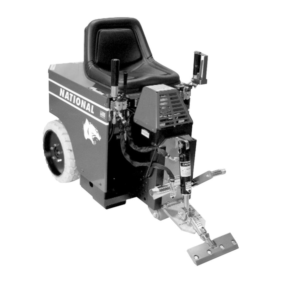
#5200 & 5200-QL PANTHER
CORDLESS RIDE-ON
FLOOR PREP SYSTEMS
Read Manual Before Operating Machine
#5200-QL
National
Flooring Equipment, Inc.
9250 X
A
N
YLON
VENUE
800-245-0267 • 763-535-8206 • F
W
S
: www.nationalequipment.com • E-M
EB
ITE
INSTRUCTION
MANUAL
• M
, MN 55445 • U.S.A.
ORTH
INNEAPOLIS
763-535-8255 • F
AX
#5200
800-648-7124
AX
: info@nationalequipment.com
AIL
®
Advertisement

Related Manuals for National 5200 PANTHER


Summary of Contents for National 5200 PANTHER
- Page 1 ® #5200 & 5200-QL PANTHER CORDLESS RIDE-ON FLOOR PREP SYSTEMS INSTRUCTION MANUAL Read Manual Before Operating Machine #5200 #5200-QL National Flooring Equipment, Inc. 9250 X • M , MN 55445 • U.S.A. YLON VENUE ORTH INNEAPOLIS 800-245-0267 • 763-535-8206 • F 763-535-8255 •...
- Page 2 5200 & 5200QL TABLE OF CONTENTS Table of Contents ....................2-4.1 Hydraulic Safe Operation ..................5-6 A. Maintaining A Safe Work Environment ..............5 B. Pressure......................5-6 C. Flammability ......................6 D. Hydraulic Fluid......................6 Rules for Safe Operation..................7-9 A. Safety Precautions/General Rules ..............7-8 B. Characteristics of a Defensive Operator ..............9 Safety Instructions ....................10 Battery/Power Pack Operation/Information ............11-15 •...
- Page 3 5200 & 5200QL TABLE OF CONTENTS Loading/Unloading ....................20-21 A.Dock Heights ......................20 B.Power-Gate ......................20 C. Ramps ........................20 D. Forklift Cups ......................21 E. Winches......................21 F. Transporting ......................21 G. Wheel Chocks ....................21 Center of Gravity ......................22 Job Site Movement ....................23-24 A. Taping Wheels....................23 B.
- Page 4 5200 & 5200QL TABLE OF CONTENTS Blade Application/Set-Up ..................30-32 A. Ceramic Set-Up....................30 B. Wood Set-Up......................30 C. Secondary Backing Carpet Set-Up ..............30 D. Foam Back Carpet Set-Up ................30 E. Double Stick Carpet Set-Up ................30 F. VCT Tile Set-Up ....................30 G. Rubber Tile Set-Up ....................30 H.
- Page 5 5200 & 5200QL TABLE OF CONTENTS N. Wheel Changing ....................40 O. Changing Filter ....................41 P. Caster Maintenance ..................41 Q. Seat Replacement....................42 R. Fuses........................42 S. Switches ......................42 T. Debris Deflector Mounting Instructions ..............42 Complete Parts List..................43-46.3 Part Numbers and Diagrams................47-59.2 A. External Parts ....................47 B.
- Page 6 HYDRAULIC SAFE OPERATION MAINTAINING A SAFE WORK ENVIRONMENT Establishing a safe working environment in and around your hydraulic equipment is just common sense. The easiest and most effective way to avoid problems is to make sure associates understand their equipment, know how to operate it safely and recognize the danger it represents if handled carelessly. A few things you must be aware of include: 1.
- Page 7 HYDRAULIC SAFE OPERATION PRESSURE (continued) iii. If the coupling was misaligned during installation, threads may have been damaged. Replace and carefully install. iv. Over torquing of a threaded connection can stretch and damage threads and mating seat angles. Over torquing can also damage the staking area of the nut. Under torquing does not allow proper sealing.
- Page 8 NOT USE” until repaired. A guard or other damaged parts should be properly repaired or replaced. For all repairs, insist on only identical National replacement parts. 13. REMOVE ALL ADJUSTING KEYS AND WRENCHES: Make a habit of checking that the adjusting keys, wrenches, etc.
- Page 9 Remove blade or keep blade lowered to the floor (disarm machine). 26. MAINTAIN LABELS AND NAME PLATES: These carry important information. If unreadable or missing, contact National for a free replacement. 27. MACHINE IS HEAVY, DO NOT DROP: Counter weights are heavy. Take caution when removing or reassembling.
- Page 10 RULES FOR SAFE OPERATION CHARACTERISTICS OF A DEFENSIVE OPERATOR • Education • Alert • Skills • Judgment • Common Sense • Recognizes the Hazards • Understands the Defense • Acts Correctly A GOOD OPERATOR IS A “DEFENSIVE” OPERATOR QUALITIES Education: Learns about the machine and the environment. Alert: Stays alert at all times…never lets guard down.
- Page 11 • Disconnect power from unit before servicing. Failure to do so can cause electrical shock. • Only use National components. Failure to do so could cause damage or serious injury. • Always be aware of support personnel and their proximity when in operation. Block off work area.
- Page 12 5200 & 5200QL BATTERY OPERATION Carrying BATTERIES Handle Blue plug 48 volt Gray 24 volt to series 48 volt Carrying Carrying Handles Handle Battery Vents Red 24 volt hook up for recharge Each power pack contains 24 volt DC current CAUTION: Electric shock hazard.
- Page 13 5200 & 5200QL BATTERY OPERATION BATTERIES (continued) REMOVING POWER PACKS - 5200 Each pack weighs 140 pounds (63.50 kilos). For safe removal, additional help may be needed. Open and secure hood. Remove all three plug connections (red, blue and gray). Never try to lift packs out of machine before completely disconnecting the blue plug in front and the gray plug on top.
- Page 14 5200 & 5200QL BATTERY OPERATION REMOVING POWER PACKS - 5200-QL Each pack weighs 185 pounds (83.91 kilos). For safe removal, additional help may be needed. Open and secure hood. Remove all three plug connections (red, blue and gray). Never try to remove packs out of machine before completely disconnecting the blue plug in front and the gray plug on top.
- Page 15 If only one charger is available, disconnect power packs from series. Charge one pack at a time. If you want to only use one charger for both packs at the same time, use National’s 48 volt system with the #5204 Extended Run Power Pack. Charge from the 48 volt blue port at the front of the power pack.
- Page 16 5200 & 5200QL BATTERY OPERATION BATTERIES (continued) CHARGING BATTERIES OUT OF THE MACHINE - 24 VOLT CHARGERS For use with #5203 and/or #5204 Power Packs. Use the same procedure as in the machine. It does not make a difference if the two packs are hooked in series (gray plug) or not, either way will work. Remember one (1) charger per pack.
- Page 17 CHARGING - 48 VOLT CHARGER READ ALL SAFETY INSTRUCTIONS BEFORE OPERATING THIS UNIT This charger is designed ONLY to be used with National’s #5204 Extended Run Power Packs. DO NOT CAUTION: use this charger with the #5203 lift-out style power packs or any other batteries. Failure to follow this warning may cause damage to charger, batteries and/or personal injury &...
- Page 18 5200 & 5200QL BATTERY OPERATION WARNING: Make sure the charger to the machine connection is made before connecting charger to a power source. Failure to do so could cause damage to the power pack and/or charger and could cause bodily injury. #5212 48 VOLT CHARGER OPERATION Always connect the battery charger to the battery prior to connecting to the A/C source.
- Page 19 5200 & 5200QL BATTERY OPERATION CAUTION (CONTINUED) b) That the extension cord is properly wired and in good condition. c) That the extension cord wire size is at least 12 gauge unless greater than 25 feet. If using an extension cord greater than 25 feet, it must be a minimum 10-gauge cord.
- Page 20 Remember packs are heavy, 120 pounds. Get help to remove packs if weight is too much or you are under lifting restrictions. Do Not drop packs. When Power packs have used their full life, they are recyclable at locations all over the US and Europe. Call National for recycle center.
- Page 21 POWER PACK WARRANTY One year warranty stamped on power pack case and on label. All warranty is null and void if power pack container is tampered with or opened. Replace/maintain only by a National certified technician. CAUTION: Remove battery when not in use, servicing and/or lifting/transporting machine.
- Page 22 WARNING: Remove battery charger’s from machine before operating. Failure to do so could cause damage to machine or bodily injury WARNING: ONLY use splitter with National’s #5212 charger. DO NOT use splitter with any other charger. Failure to follow this warning could cause damage to charger, property and/or bodily injury.
- Page 23 WARNING: Remove the power cord from power source before disconnecting the power pack and/or the splitter from the charger. WARNING: ONLY use splitter with National’s #5212 charger. DO NOT use splitter with any other charger. Failure to follow this warning could cause damage to charger, property and/or bodily injury.
- Page 24 5200 & 5200QL BATTERY CHARGER INSTRUCTION SINGLE CHARGING Charging time: range 2 to 4½ hours depending on the level of discharge of the power pack. Page 13.1h...
- Page 25 5200 & 5200QL BATTERY OPERATION COMMONLY ASKED QUESTION 1. Question: When the charging battery has been fully discharged will it take a memory set? Answer: No, the design of this battery allows charging at any stage of discharge without memory problems.
- Page 26 Colored plugs can not be intermixed. 11. Question: Can the batteries be replaced in packs? Answer: Yes, but only by a qualified National technician or service center. Never try to replace yourself. 12. Question: Can I leave the charger on too long? Answer: No, our charging system is designed to read batteries state of charge constantly if left on for long periods of time (over the weekend) it will not heat batteries or cause over charging problem.
- Page 27 5200QL FEATURES/SPECIFICATIONS #5200-QL Control Lever Forward/Reverse Neutral Break Control Lever Forward/Reverse Neutral Break Power On/Off Switch Cutting Head Cylinder Lift DC Motor Pump Compartment Adjustable Extra weight Slide Plate compartments (both sides) #5200-QL Flip-up back lid for quick and easy Foot Rest battery changing.
- Page 28 5200QL FEATURES/SPECIFICATIONS VIBRATION/SOUND DATA VIBRATION DATA: Axis Stationary Moving >0.1 Vector >0.1 Whole Body Vibration Levels in m/s^2 Axis Left Right Vector Sum Hand/Arm Vibration Levels in m/s^2 SOUND DATA: Stationary 77.0 Moving 73.0 Operator Sound Level dBA ref. 20 Pa Page 16.1...
- Page 29 5200 & 5200QL OPERATING CONTROLS POWER ON/OFF SWITCH (FIGURE A) Never use the power on/off switch as a method for speed control. Speed control is achieved by the hydraulic valve only. Using the on/off switch repeatedly will cause excessive wear, causing premature replacement of electrical components.
- Page 30 5200 & 5200QL OPERATING CONTROLS POWER KILL SWITCH (FIGURE A) Kill Switch The power kill switch is designed to kill the power to the system when the machine is in storage. Also removing the blue plug is a good idea. This will help to keep someone from operating the machine when it shouldn’t be.
- Page 31 5200 & 5200QL OPERATING CONTROLS LOWERING HOOD - 5200 To lower hood, stabilize hood with one hand and pull on the hood stop slide with other hand (See Figure A). Note: hood may need to be positioned before hood stop will release. Carefully lower hood removing hands out of the way before the hood is completely closed.
- Page 32 5200 & 5200QL OPERATIONAL TIPS CASTER Keep clean and free of debris, make sure it can move freely. Clean as needed. Inspect before each use. Grease once a month. Moving a "weighted" machine only on the front caster and not on the cutting head or the Front Wheel Assembly can seem to make the machine turn sluggish.
- Page 33 5200 & 5200QL LOADING/UNLOADING • Always remove blade and cutting head when machine is being moved or transported • Cutting head and slide plate can be removed to make the machine more compact. • NEVER leave machine unattended on an incline. •...
- Page 34 5200 & 5200QL LOADING/UNLOADING FORKLIFT CUPS There are two forklift cups mounted under the front of the machine (See Figure A). Slide fork lift forks through forklift cups. Slide forks all the way back to touch the rear tire (See Figure B). Before lifting machine, secure machine to fork lift with heavy 3000 lb.
- Page 35 5200 & 5200QL CENTER OF GRAVITY Be aware of your surroundings and machines operating angels. When changing from a low slide plate to a high slide plate setting or a low cutting head angle to a high cutting head angle, the operating “attitude” of the machine changes.
- Page 36 5200 & 5200QL JOB SITE MOVEMENT • Always remove blade and cutting head when machine is being moved or transported • Cutting head and slide plate can be removed to make the machine more compact. • NEVER leave machine unattended on an incline. •...
- Page 37 5200 & 5200QL JOB SITE MOVEMENT TO MOVE MACHINE WITHOUT POWER (PUSHING MACHINE) Forward: To move the machine forward, levers need to be pushed forward. To lock levers in place, connect a bungee-strap from each lever (pushing levers forward), pulling straps down to and connecting to the front plate (See Figure A).
- Page 38 5200 & 5200QL WHEEL SIZES WHEEL SIZE(FIGURE A) The 18'' wheel comes standard on the machine. This wheel will work on all job types of application and heavy debris build-up (vct, ceramic etc.). It also works best for slippery/slimy residue, ie. double stick. The 13'' and 16'' wheels are used to slow the speed of the machine, lower the amperage and increase torque.
- Page 39 5200 & 5200QL ADDING ADDITIONAL WEIGHT FRONT WEIGHT Adding weight to the front of the machine is necessary for difficult to remove goods such as, VCT, VAT, ceramic, thin-set, wood or increase traction on wet, dusty or slick surfaces. Machine includes twelve 36 lb.
- Page 40 5200 & 5200QL CUTTING HEAD & BLADES DIALING IN THE MACHINE Dialing in the machine is matching the correct cutting head, blade size, blade angle and added weight to the machine to make the material removal as easy as possible. For every material being removed, there is an optimum blade width, thickness, sharpness, angle and bevel (bevel up or bevel down).
- Page 41 5200 & 5200QL CUTTING HEAD & BLADES WEIGHT VS. SHARPNESS The most common way to compensate for a dull blade is to add more weight and raise the blade angle (see re-scrape setting). Weight allows dull blades to be used to a point. Weight also causes blades to dull and break easier.
- Page 42 5200 & 5200QL CUTTING HEAD & BLADES CUTTING HEAD INSERTION With machine off, insert desired cutting head into cutting head holder. Secure with cutting head clip. SHANK BLADE INSERTION Shank blades do not require a cutting head. Insert desired shank blade into cutting head holder. Secure with cutting head clip.
- Page 43 5200 & 5200QL BLADE APPLICATION/SET-UP CERAMIC SET-UP Slide plate should be set low, 1/4" to 1/2" off the floor. Use a Shank Blade or a Shank Blade with a carbide tip. WOOD SET-UP Slide plate should be set low, 1/4" to 1/2" off the floor. Use Shank Blades, Shank Blades with carbide tips or a 6"or 8"...
- Page 44 5200 & 5200QL BLADE APPLICATION/SET-UP RE-SCRAPING SET-UP Slide plate should be set high, 6'' to 8'' off the floor. Use a Cutting Head from 8" to 27" with Scraper Blades to match cutting head size. A 15" scrapper blade would use a 14" Cutting Head. Razor Blades are faster but a Cutting Head from 8"...
- Page 45 5200 & 5200QL BLADE APPLICATION/SET-UP DITCHING CROSS ROOM DITCHING When removing hard to remove ceramic, Vct or vat, cross-room ditching will help to make the removal easier. Using a blade 2" to 6" in width, make ditches 1' to 2' apart in the same direction the machine will be removing the goods (See Figure A).
- Page 46 5200 & 5200QL BLADES TYPES OF BLADES PREMIUM HIGH TEMPERED BLADES (.062) Works on all glued down carpets, VCT, VAT, rubber tile, cork, re-scraping adhesive, elastomeric coatings. Great for floor accumulations. Ultra high quality spring steel is extra hard for long blade life between sharpening.
- Page 47 5200 & 5200QL BLADES BLADE SHARPENING Dull blades greatly reduce cutting ability. Re-sharpen or replace as needed. In use, blades develop a back-bevel (See Figure A). When re-sharpening, blade will not be truly sharp until all back-bevel is gone. Note: Thinner blades are easier to sharpen, but they also break easier. •...
- Page 48 5200 & 5200QL BLADES Part # Description Application Thickness #135 5" x 16" Blade Rubber back carpet on wood or concrete floors, excellent for .062 cleanup and longer durability #147 4" x 6" Blade Tile or linoleum on concrete floors .062 #148 5"...
- Page 49 5200 & 5200QL BLADES Part # Description Application Thickness #7075-8 2'' x 8'' Tapered Cutting Head Shank .300 The long taper works great on tough wood floors (glued & nailed). #7075-11 2'' x 11'' Tapered Cutting Head Shank .300 The long length allows the blade to easily slide under tough material. Works well on most ceramics and VCT.
- Page 50 5200 & 5200QL MACHINE MAINTENANCE SLIDE PLATE To Remove Slide Plate 1. Disconnect machine from power. 2. Remove slide plate pin. Remove cutting head bolt. Remove cylinder from slide plate. Remove slide plate. 1. Disconnect machine from power. 2. Unplug hydraulic lines from cylinder. A small amount of oil leak out of lines. Cap lines or bleed into a container.
- Page 51 5200 & 5200QL MACHINE MAINTENANCE SIDE AND REAR PANELS To Remove A Panel 1.Lift hood and secure in place. 2.Using proper wrench size, remove desired side or rear panel. OIL LEVEL To Check Oil Level 1. Remove Breather Dip Stick (See Figure A) 2.
- Page 52 5200 & 5200QL MACHINE MAINTENANCE HOSE CHANGE OUT To Remove Or Change A Hose 1. Disconnect machine from power. 2. Remove hood. 3. Using proper wrench size, remove hose from fitting. 4. When replacing, make sure O-ring is properly seated on hose fitting. FOOT PEG To Remove Or Replace Foot Peg 1.
- Page 53 5200 & 5200QL MACHINE MAINTENANCE HYDRAULIC CYLINDER CHANGE OUT 1. Disconnect machine from power. 2. Disconnect cylinder lines. Have a container ready to catch oil from lines. 3. Remove cylinder securing hexhead bolt from lower cutting head support. 4. Remove clips and pin from cylinder and slide plate. 5.
- Page 54 5200 & 5200QL MACHINE MAINTENANCE CHANGING FILTER-Filter should be replaced yearly. 1. Remove the three filter cover bolts (See Figure A). 2. Lift out the filter (See Figure B). 3. Replace with new filter. 4. Replace cover spring. 5. Replace and firmly tighten bolts. Figure A Figure B CASTER MAINTENANCE...
- Page 55 5200 & 5200QL MACHINE MAINTENANCE SEAT REPLACEMENT 1. Remove two button hexhead screws on each side of the hood (4 times). 2. Lift hood off. 3. Remove seat. 4. To replace seat, set seat on top of hood. 5. Replace the four 5/16 button hexhead screws from underneath the hood. 6.
- Page 56 Note: Number in parenthesis ( ) is the amount needed on each machine. Parts are sold individually therefore order the number of parts needed.
- Page 57 5200 & 5200QL COMPLETE PARTS LIST PART # DESCRIPTION 5110-111 SEAT 5110-114 HYDRAULIC WHEEL MOTOR (2) 5110-114A HIGH SPEED HYDRAULIC WHEEL MOTOR (2) 5110-114-2 WHEEL MOTOR FITTING (4) 5110-114-5 WHEEL MOTOR SET OF SEALS (NOT SHOWN) 5110-115 SINGLE SPOOL CONTROL 5110-115-1 SINGLE SPOOL SEAL KIT (NOT SHOWN) 5110-115-2...
- Page 58 5200 & 5200QL COMPLETE PARTS LIST PARTS LIST (continued) PART # DESCRIPTION 5200-1G DOUBLE PUMP GASKET 5200-3 FUSE BRACKET 5200-4 FUSE HOLDER 5200-5 100 AMP MOTOR FUSE 5200-6 FUSE COVER 5200-7 SHOCK PAD 5200-10-3 HOOD STOP SLIDE 5200-10-4 HOOD SLIDE SPACER 5200-11-LH SINGLE SPOOL MOUNT 5200-11-RH...
- Page 59 5200 & 5200QL COMPLETE PARTS LIST PARTS LIST (continued) PART # DESCRIPTION 5200-166R RIGHT HANDLE 5200-191 SWITCH ASSEMBLY 5200-191A SWITCH SECURING NUT 5200-194 DOUBLE WHEEL CASTER ASSEMBLY (GREY) 5200-194A WHEEL ONLY (2) (NOT SHOWN) 5200-217 BACK-UP BEEPER BRACKET 5200-254 LOWER CYLINDER LINE 5200-255 UPPER CYLINDER LINE 5200-258...
- Page 60 5200 & 5200QL COMPLETE PARTS LIST PARTS LIST (continued) PART # DESCRIPTION 5200QL-600 SHROUD UPGRADE KIT (NOT SHOWN) 5200QL-700 FRONT HOOD UPGRADE KIT 5200QL-710 VALVE UPGRADE KIT ASSEMBLY 5200-VI INSTRUCTION VIDEO (NOT SHOWN) 5205 24 VOLT CHARGER 5212 48 VOLT CHARGER, 50/60 CYCLE, 100 TO 240 VOLT 70602 INSTRUCTION MANUAL TUBE 70603...
- Page 61 5200 & 5200QL COMPLETE PARTS LIST PARTS LIST (continued) PART # DESCRIPTION 73406 1/2-13 X 1-1/4 HEXHEAD BOLT (5) 73407 1/2-13 X 1-1/2 HEXHEAD BOLT (8) 73408 1/2-13 X 1 HEXHEAD BOLT (2) 73410 1/2-13 X 3-1/2 HEXHEAD BOLT 73414 1/2-13 X 7 HEXHEAD BOLT (2) 73430 1/2-20 NYLON LOCK NUT (10)
- Page 62 5200 & 5200QL COMPLETE PARTS LIST BLADES & CUTTING HEADS (continued) PART # DESCRIPTION 6260-BD 3" X 6" HEAVY DUTY DITCHING 6281 3'' X 8'' HEAVY DUTY BLADE 6282 3'' X 14'' HEAVY DUTY BLADE 6283 3'' X 27'' HEAVY DUTY BLADE 6284 3'' X 12'' HEAVY DUTY BLADE 6285...
- Page 63 L162 48 VOLT VDC LABEL L165 BLADE APPLICATION LABEL L168 INSTRUCTION LABEL L169 PRODUCT NUMBER LABEL L172 LOWERING HOOD INSTRUCTIONS LABEL L174C 5200-QL LABEL L176 NATIONAL LABEL, LARGE L311 BATTERY LABEL L316 OIL/TEMP ON LABEL L317 THROTTLE LABEL Page 46.3...
- Page 64 PART NUMBERS & DIAGRAMS (5200 ONLY) EXTERNAL PARTS 270-1 73006 25-RH 73345 165-3L Front Weight Compartment 165-3R 70602 70603 PART # DESCRIPTION 5110-111 Seat 73214 5110-165-3L Footrest Extension Bracket, Left 5110-165-3R Footrest Extension Bracket, Right 5110-180 Foot Peg (2) 5200-25-LH Left Side Panel (Not Shown) 5200-25-RH Right Side Panel...
- Page 65 PART NUMBERS & DIAGRAMS (5200-QL ONLY) HOOD & EXTERNAL PARTS 73201 73203 73207 73212 PART # DESCRIPTION PART # DESCRIPTION 5200QL-25 Right Side Panel 5200QL-40 Battery Guide, Right & Left (2) 5200QL-26 Left Side Panel (Not Shown) 5200QL-41 Battery Guide Center 5200QL-27 Main Base 5200QL-42...
- Page 66 PART NUMBERS & DIAGRAMS (5200-QL ONLY) HOOD LEVER PARTS & FRONT HOOD UPGRADE KIT 73005 73007 73008 73008 73005 5200QL-34 73008 73005 73008 73014 73007 73025 5200QL-700 5200QL-700 PART # DESCRIPTION PART # DESCRIPTION 5200QL-30 Hood Lever Assembly 73005 1/4-20 x 1/2 Hexhead Bolt (3) 5200QL-31 Hood Lever Only 73007...
- Page 67 5200 & 5200QL PART NUMBERS & DIAGRAMS BEEPER & HOOD PARTS 70602 74501 74510 74429 -218 74513 74513 73029 73201 -10-3 -10-4 73202 73203 73345 73207 -10-3 73213 PART # DESCRIPTION PART # DESCRIPTION 5110-218 Back-Up Beeper Switch 73202 Button Head Star Washer (20) 5200-10-3 Hood Stop Slide 73203...
- Page 68 5200 & 5200QL PART NUMBERS & DIAGRAMS -127 ELECTRIC BOX & -125 -126 -118-4 -120 BATTERY CONNECTOR -118-3 -118-5 PARTS -118-6 -119 -118-7 -128 -118-13 -118-1A -118-17 -119-1 74412 -118-1 -120 118-11 118-10 -120-1 -118-8 -118-9 73082 73008 -129 -118 -QL-129 PART # DESCRIPTION...
- Page 69 5200 & 5200QL PART NUMBERS & DIAGRAMS MOTOR & FUSE PARTS 73035 73035 73201 73008 73008 73204 73006 73006 73008 73008 PART # DESCRIPTION 72391 5200-1C Motor Fan Cover 5200-1F Motor Fan 5200QL-1A 5200-3 Fuse Bracket 73008 1/4 Nylon Lock Nut (4) 5200-4 Fuse Holder 5200-5...
- Page 70 5200 & 5200QL PART NUMBERS & DIAGRAMS GEAR PUMP PARTS 70905-D4 -111 73214 73204 73204 73214 73203 73203 PART # DESCRIPTION 5200-1G Double Pump Gasket 5200-111 90° Pump Fitting 70905-D4 Double Gear Pump 73203 3/8 SAE Flat Washer (2) 73214 3/8-16 x 1 Button Head Cap Screw (2) 73204 3/8 Split Lock Washer (2)
- Page 71 5200 & 5200QL PART NUMBERS & DIAGRAMS WHEEL PARTS 5110-405 18'' Wheel & Rim 5200-409 16'' Wheel & Rim 5110-408 13'' Wheel & Rim 5200-261-1 -114 -114-2 -117 73047 73131 -114A -117-2 73430 PART # DESCRIPTION PART # DESCRIPTION 5110-114 Hydraulic Wheel Motor (2) 5110-408 13'' Wheel &...
- Page 72 5200 & 5200QL PART NUMBERS & DIAGRAMS CONTROL LEVER PARTS (OLD STYLE) -270-1 -11-LH 80110 -11-RH 80110 -166G -191A -166L -166R -191 74433 -166H -117 73207 73023 73008 -217 73207 5110-271 5110-272 73260 PART # DESCRIPTION PART # DESCRIPTION 5110-271 Lever Bracket (3) 5200-191 Switch Assembly...
- Page 73 5200 & 5200QL PART NUMBERS & DIAGRAMS CONTROL LEVER PARTS (NEW STYLE) 5200QL-11-RH 5200QL-11-LH 73213 73202 5200QL-12 5110-272 73322 73321 73322 73320 5200QL-13 73227 73227 5200QL-14 73020 73235 73235 5110-271 PART # DESCRIPTION 5110-271 Lever Bracket (3) 5110-272 Cylinder Lift Lever Only 5200QL-11-LH Single Spool Valve 5200QL-11-RH...
- Page 74 5200 & 5200QL PART NUMBERS & DIAGRAMS SINGLE SPOOL & HOSE PARTS -263 70651 73021 70651 73008 -115 73308 73008 73021 -116-4 -115-2 -116-5 -262 -261 PART # DESCRIPTION PART # DESCRIPTION 5200-263 Suction Line (2) 5110-115 Single Spool Control 70651 Valve Body Plug (4) 5110-115-1...
- Page 75 5200 & 5200QL PART NUMBERS & DIAGRAMS DOUBLE SPOOL & HOSE PARTS -262 -263 70651 73021 73008 73021 70651 -261-1 -116 -116-2 -270-2 -264 -116-4 -272-1 -270-1 -116-5 -115-2 -254 -255 73308 -261 PART # DESCRIPTION PART # DESCRIPTION 5110-115-2 3/16'' Valve Pin (2) 5200-261 Wheel Motor Line (2)
- Page 76 5200 & 5200QL PART NUMBERS & DIAGRAMS FILTER & TANK PARTS -266 -235 -237-1 -233 -236-1 (#236-1 is Inside -236 #236 Filter Housing -237-1A Assembly) -238 -237-1B -237 -235-2 -235-1 -235-1 -164A -164B -157 -235-3 PART # DESCRIPTION PART # DESCRIPTION 5110-164A Tank Hose...
- Page 77 5200 & 5200QL PART NUMBERS & DIAGRAMS SLIDE PLATE, CYLINDER & DEFLECTOR PARTS -252 -251 -166 -253-R -250 -253 73407 -170 73402 73410 -167 73340 73408 -258 73403 5110-250-3 PART # DESCRIPTION PART # DESCRIPTION 5110-253R Cylinder Restricter Fitting 5110-166 Slide Plate 5200-258 Debris Deflector...
- Page 78 5200 & 5200QL PART NUMBERS & DIAGRAMS CASTER & FOOT PEG PARTS 5200-194 5200-194A 73402 73406 73406 73402 5110-180 73204 73204 73208 73208 73207 73207 PART # DESCRIPTION PART # DESCRIPTION 73207 3/8-16 Nylon Lock Nut (2) 5110-180 Foot Peg (2) 5200-194 Double Wheel Caster Assembly 73208...
- Page 79 5200 & 5200QL PART NUMBERS & DIAGRAMS WEIGHTS Rear Weight Compartment 73406 5110-404 Front Weight Compartments 5200-400-2 73414 -400-4 -400-5 PART# DESCRIPTION PART # DESCRIPTION 5110-404 Rear Weight 5200-400-5 SAE 5/8 Flat Washer, Weight (2) 5200-400-2 Front Weight Individually (12) 73406 1/2-13 x 1-1/4 Hexhead Bolt 5200-400-4...
- Page 80 5200 & 5200QL PART NUMBERS & DIAGRAMS CHARGER PARTS -118-8 -118-9 5205-1 -118-11 5205-2 5205-3 -118-10 -118-11 5205-6 -118-16 5205-1 5205 73087 73008 5205-4 5212 73014 5207-4 73007 73008 73506 PART # DESCRIPTION PART # DESCRIPTION 5200-29 Battery Bumper (6) 5205-2 Replacement Strain Relief 5200-118-8...
- Page 81 5200 & 5200QL PART NUMBERS & DIAGRAMS EXTERNAL PARTS 5203 POWER PACK Standard Power Pack • Recharges quickly 5203-1 DEEP CYCLE BATTERY ONLY 5204 EXTENDED RUN POWER PACK Twenty five percent more cycle life • Up to fifty percent more run time • Has the ability to take a rapid charge without affecting the cycle life •...
- Page 82 5200QL PART NUMBERS & DIAGRAMS #5200-QL-500 BATTERY CART ASSEMBLY -500H -500G -505 -507 -503 -507 73330 -500F 73407 -502 73402 Left Wheel Fixed 73407 73233 -507 -507 Wheel 73207 Fixed -501 Right Wheel Swivel -506 Wheel -504 Swivel PART # DESCRIPTION PART # DESCRIPTION...
- Page 83 5200 & 5200QL LABELS L155 L148 L162 L165 L33C L08-1 L106 L33B L137 L142 PART # DESCRIPTION PART # DESCRIPTION L08-1 Stand Clear Label (2) L137 Disarm Machine Label L33B Caution Moving Parts Label (2) L142 Trailer Hitch Label L33C Instruction Manual Label L148 Caution General Info Label...
- Page 84 5200 & 5200QL LABELS L106 L106 L161 L153 L157 L101 L159 L156 L230 L172 L168 L166 PART # DESCRIPTION PART # DESCRIPTION Disconnect Before Service (2) L161 +/+ Label L101 Kill Switch Label L168 Instruction Label L106 Pinch Point Label (4) L169 Product Number Label L153...
- Page 85 PART # DESCRIPTION PART # DESCRIPTION L33D Authorized Personnel Label L141 Flag Made In USA Label (2) Blade Lift Label L174C 5200-QL Label L118 Operator Must Be Seated Label (2) L176 National Label, Large L137 Disarm Machine Label (2) Page 62...
- Page 86 5200 & 5200QL ACCESSORIES 5205 BATTERY CHARGER 5205 Battery Charger 24 Volt, 110 V 5205-W Battery Charger 24 Volt, 220/240, CE Approved For use with #5203 and/or #5204 Power Packs 5205 5212 Battery Charger 48 Volt, 50/60 Cycle, 100 to 240 Volt NOTE: O #5204 P NLY USE WITH...
- Page 87 5200 & 5200QL BLADES & CUTTING HEADS CUTTING HEADS Swivel heads rotate to use the second sharp edge of the blade without having to remove the blade. Swivel head allows blade to stay in contact with the floor. 7050-6 6'' CUTTING HEAD 7050-8 7050-10 7050-8RBH...
- Page 88 5200 & 5200QL BLADES & CUTTING HEADS STRAIGHT SHANK BLADES The ultimate for tough removals. Works well for ceramic, wood and thick epoxy. 7070-2 2'' STRAIGHT SHANK BLADE 7070-3 3'' STRAIGHT SHANK BLADE 7070-4 4'' STRAIGHT SHANK BLADE 7070-6 6'' STRAIGHT SHANK BLADE ANGLE SHANK/SHOE BLADES The same application as the #7070 blades, but is mounted at an angle to achieve the optimum shear point for optimum performance.
- Page 89 5200 BATTERY BOX WIRING Ø0.880 THRU (2X) 26.112 1.750 16.626 PLUG BATTERY COVER #1 TOP VIEW GRAY PLUG BLUE PLUG PLUG Ø0.880 THRU (2X) 16.626 BATTERY COVER #2 TOP VIEW Page 65.1...
- Page 90 5200 CONTACTOR & ON/OFF SWITCH WIRING Page 65.2...
- Page 91 5200 & 5200QL MATERIAL SAFETY DATA Page 66...
- Page 92 5200 & 5200QL MATERIAL SAFETY DATA Page 67...
- Page 93 5200 & 5200QL MATERIAL SAFETY DATA Page 68...
- Page 94 5200 & 5200QL MATERIAL SAFETY DATA Page 69...
- Page 95 5200 & 5200QL MATERIAL SAFETY DATA Page 70...
- Page 96 5200 & 5200QL MATERIAL SAFETY DATA Page 71...
- Page 97 In no event shall National be liable, or in any way responsible for any damage or defects in the product which were caused by repairs or attempted repairs performed by anyone other than National. Nor shall National be liable, or in any way responsible, for any incidental or consequential, economics or property damage.
- Page 98 Telephone Number Approximate Usage (hours) Problems Encountered Check One: Repair Do you wish to be contacted before repairing Return Contact National if a loaner is needed Return Authorization Number Date required, contact National Customer Number if known Purchased From if not directly from National...
- Page 99 5200 & 5200-QL BLADE ORDER FORM Part # Description Thickness Quantity #135 5" x 16" Blade .062 #147 4" x 6" Blade .062 #148 5" x 6" Blade .062 #363-2 3/4'' x 8'' Razor/Scraper Blade (50/pkg) .032 #368-8 7/8'' x 8'' Razor/Scraper Blade (50/pkg) .045 #368-12 7/8'' x 12'' Razor/Scraper Blade (50/pkg)
- Page 100 Online: www.nationalequipment.com All orders and payment terms to be verified prior to shipping. National Flooring Equipment, Inc. • 9250 Xylon Avenue North • Minneapolis, MN 55445 U.S.A. Phone 800-245-0267 or 763-535-8206 • Fax 800-648-7124 or 763-535-8255 Web Site: www.nationalequipment.com • E-Mail: info@nationalequipment.com...
Need help?
Do you have a question about the 5200 PANTHER and is the answer not in the manual?
Questions and answers