Table of Contents
Advertisement
Quick Links
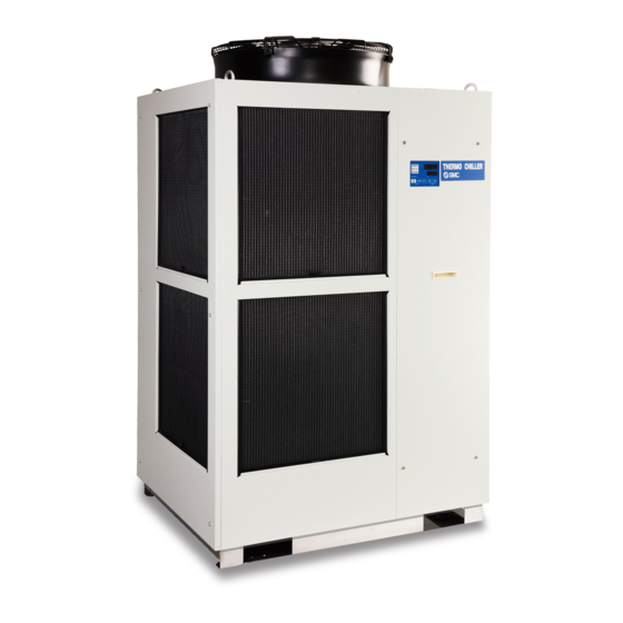
Thermo-chiller
Air-cooled 460 V Type
HRS 200 A
Cooling capacity
200
20.5 kW
A
Nil
F
G (With Rc-G conversion fitting)
N
NPT (With Rc-NPT conversion fitting)
Specifications
Model
Cooling method
Refrigerant
Refrigerant charge
Control method
Ambient temperature/Altitude *
1, 7
Circulating fluid *
1, 2
Set temperature range *
1
Cooling capacity *
3, 7
Heating capacity *
4
Temperature stability *
5
Rated flow (Outlet)
Pump
Maximum flow rate
capacity
Maximum pump head
Minimum operating flow rate *
Tank capacity
Circulating fluid outlet, circulating fluid return port
Tank drain port
Supply side pressure range
Automatic
Supply side fluid temperature
fluid fill
system
Automatic fluid fill port
(Standard)
Overflow port
Fluid contact material
Power supply
Rated current
Applicable earth leakage
breaker (Standard)
Sensitivity of leak current mA
Rated operating current *
5
Rated power consumption *
5
Noise level (Front 1 m/Height 1 m) *
5
Waterproof specification
Accessories
Weight (dry state)
HRS200
How to Order
Cooling method
Air-cooled refrigeration
Pipe thread type
Rc
Power supply
46
3-phase 460 VAC (60 Hz)
HRS200-Am-46-mS
Air-cooled refrigeration
R410A (HFC)
kg
°C
Temperature: –5 to 45, Altitude: less than 3000 m
Tap water, 15% Ethylene glycol aqueous solution, Deionized water
°C
kW
kW
°C
L/min
45 (0.45 MPa)
L/min
m
L/min
6
L
Rc1 (Symbol F: G1, Symbol N: NPT1)
Rc3/4 (Symbol F: G3/4, Symbol N: NPT3/4)
MPa
°C
Rc1/2 (Symbol F: G1/2, Symbol N: NPT1/2)
Rc1 (Symbol F: G1, Symbol N: NPT1)
Metal
Stainless steel, Copper (Heat exchanger brazing), Brass, Bronze
Resin
PTFE, PU, FKM, EPDM, PVC, NBR, POM, PE, NR
3-phase 460 VAC (60 Hz)
Allowable voltage range ±10% (No continuous voltage fluctuation)
A
A
kW(kVA)
dB(A)
Alarm code list sticker 1 pc. (English),
Operation Manual (for installation/operation) 1 pc. (English),
Y-strainer (40 meshes) 25A, Barrel nipple 25A,
Anchor bolt fixing brackets 2 pcs. (including 6 M8 bolts) *
kg
Series
Standard Type
46
S
Option 2
Nil
W
Option 1
Nil
A
With caster adjuster-foot
K *
1
*1 This is a manual fluid fill port that is different from the automatic
fluid fill port. Fluid can be supplied manually into the tank without
removing the side panel. (Fluid can be supplied manually for
models without option K if the side panel is removed.)
1.65
PID control
5 to 35
20.5
5.3
±1
130
50
25
25
0.2 to 0.5
5 to 35
30
30
14.2
9.1 (11.4)
75
IPX4
8
214
INFORMATION
None
SI unit only
None
With fluid fill port
*1 When the ambient temperature or circulating fluid
temperature is 10°C or below, refer to "Operation at
low ambient temperature or low circulating fluid tem-
perature" (page 14).
*2 Use fluid in condition below as the circulating fluid.
Tap water: Standard of The Japan Refrigeration And
Air Conditioning Industry Association (JRA GL-02-
1994)
15% ethylene glycol aqueous solution: Diluted with
clean water, without any additives such as antisep-
tics.
Deionized water: Electric conductivity 1 μS/cm or
higher (Electric resistivity 1 MΩ·cm or lower)
*3 q Ambient temperature: 32°C, w Circulating fluid:
Tap water, e Circulating fluid temperature: 20°C, r
Circulating fluid flow rate: Rated flow, t Power sup-
ply: 460 VAC
*4 q Ambient temperature: 32°C, w Circulating fluid:
Tap water, e Circulating fluid flow rate: Rated flow,
r Power supply: 460 VAC
*5 q Ambient temperature: 32°C, w Circulating fluid:
Tap water, e Circulating fluid temperature: 20°C, r
Load: Same as the cooling capacity, t Circulating
fluid flow rate: Rated flow, y Power supply: 460 VAC,
u Piping length: Shortest
*6 Fluid flow rate to maintain the cooling capacity. If the
actual flow rate is lower than this, install a bypass
piping.
*7 If the product is used at altitude of 1000 m or higher,
refer to "Operating Environment/Storage Environ-
ment" (page 13) Item 13 "* For altitude of 1000 m or
higher."
*8 The anchor bolt fixing brackets (including 6 M8 bolts)
are used for fixing to wooden skids when packaging
the thermo-chiller. No anchor bolt is included.
(Pending for UL Standards)
18-E700
Advertisement
Table of Contents

Related Manuals for SMC Networks HRS200 Series


Summary of Contents for SMC Networks HRS200 Series
-
Page 1: Specifications
INFORMATION Thermo-chiller Standard Type (Pending for UL Standards) Air-cooled 460 V Type How to Order HRS 200 A Cooling capacity Option 2 20.5 kW Cooling method None SI unit only Air-cooled refrigeration Option 1 Pipe thread type None With caster adjuster-foot G (With Rc-G conversion fitting) With fluid fill port NPT (With Rc-NPT conversion fitting) -
Page 2: Cooling Capacity
HRS200 Series Standard Type Cooling Capacity Pump Capacity HRS200-Am-46-mS HRS200-Am-46-mS Usable flow rate range Ambient temperature 32°C 0.45 Outlet Ambient temperature 40°C Eye bolt M12 (4 places) Ambient temperature 45°C Operation display panel Facility water outlet Rc1 Return port Handle Handle Ventilation air outlet 50 60 70 80 90 100 110 120 130... -
Page 3: Cable Specifications
HRS200 Series Thermo-chiller Standard Type Recommended External Piping Flow External piping circuit is recommended as shown below. Thermo-chiller automatic fluid Fluid supply fill port Circulating fluid outlet User’s equipment Circulating fluid return port Overflow port To wastewater collection pit Tank drain port * Ensure that the overflow port is connected to the wastewater collection pit in order to avoid damage to the tank of the thermo-chiller. -
Page 4: Operation Display Panel
HRS200 Series Standard Type Operation Display Panel List of Function The basic operation of this unit is controlled through the operation display panel on the front of the product. Function Outline Displays the current and set temperature of the 1 Main display circulating fluid, discharge pressure of the circulating fluid. -
Page 5: Communication Functions
HRS200 Series Thermo-chiller Standard Type Communication Functions Contact Input/Output Item Specifications Connector type M3 terminal block Insulation method Photocoupler Rated input voltage 24 VDC Input signal Operating voltage range 21.6 to 26.4 VDC Rated input current 5 mA TYP Input impedance 4.7 kW Rated load voltage 48 VAC or less/30 VDC or less... - Page 6 HRS200 Series * Options have to be selected when Options ordering the thermo-chiller. It is not possible to add them after purchasing the unit. Option symbol With Caster Adjuster-foot HRS200 A 46 A S With caster adjuster-foot Unfixed casters and adjuster feet stops are mounted Option symbol With Fluid Fill Port HRS200 A...
-
Page 7: Optional Accessories
HRS200 Series Optional Accessories q Piping Conversion Fitting This is a fitting to change the port from Rc to G or NPT. · Circulating fluid outlet, Circulating fluid return port, Overflow port Rc1 → NPT1 or G1 · Drain port Rc3/4 → NPT3/4 or G3/4 ·... - Page 8 HRS200 Series e Electric Conductivity Control Set The set indicates and controls the electric conductivity of the circulating fluid. Refer to the Operation Manual for details. Part no. Applicable model Measurement range of electric conductivity 2.0 to 48.0 μS/cm HRS-DI006 HRS200-A-46-S (292) 5.0 to 45.0 μS/cm...
- Page 9 HRS200 Series Optional Accessories t Snow Protection Hood Stainless steel snow protection hood for air-cooled chiller. According to the mounting direction of the snow protection hood, the ventilation from the fan can be selected from four directions, front, rear, left and right. Right Left Rear...
- Page 10 HRS200 Series y Particle Filter Set Removes foreign matter in the circulating fluid. This set cannot be directly connected to the thermo-chiller. Install it in the user’s piping system. Refer to the Operation Manual for details. Particle Filter Set HRS PF005 H Fluid Tap water Max.
-
Page 11: Wired Remote Controller
HRS200 Series Optional Accessories u Wired Remote Controller When the wired remote controller is connected to the thermo-chiller, the operation start/stop setting or the set temperature can be changed from a place apart from the thermo-chiller. For details, refer to the Operation Manual. Wired Remote Controller HRS CV004 1 Accessories... -
Page 12: Cooling Capacity Calculation
HRS200 Series Cooling Capacity Calculation Required Cooling Capacity Calculation Example 1: When the heat generation amount in the user’s equipment is known. The heat generation amount can be determined based on the power consumption or output of the Q: Heat generation heat generating area —... -
Page 13: Heating Capacity
HRS200 Series Cooling Capacity Calculation Example 3: When there is no heat generation, and when cooling the object below a certain temperature and period of time. Heat quantity by cooled substance (per unit time) Q : Unknown [W] ([J/s]) Example of current measurement units (Reference) Cooled substance : Water Heat quantity by cooled substance (per unit time) Q : Unknown [cal/h] →... -
Page 14: Specific Product Precautions
HRS200 Series Specific Product Precautions 1 Be sure to read this before handling the products. For safety instructions and tempera- ture control equipment precautions, refer to the “Handling Precautions for SMC Prod- ucts” and the “Operation Manual” on the SMC website: https://www.smcworld.com Design Operating Environment/Storage Environment Warning... -
Page 15: Operation At Low Ambient Temperature Or Low Circulating Fluid Temperature
HRS200 Series Specific Product Precautions 2 Be sure to read this before handling the products. For safety instructions and tempera- ture control equipment precautions, refer to the “Handling Precautions for SMC Prod- ucts” and the “Operation Manual” on the SMC website: https://www.smcworld.com Transportation/Carriage/Movement Operation at Low Ambient Temperature or Low Circulating Fluid Temperature... - Page 16 HRS200 Series Specific Product Precautions 3 Be sure to read this before handling the products. For safety instructions and tempera- ture control equipment precautions, refer to the “Handling Precautions for SMC Prod- ucts” and the “Operation Manual” on the SMC website: https://www.smcworld.com Mounting/Installation Piping Warning...
-
Page 17: Operation
HRS200 Series Specific Product Precautions 4 Be sure to read this before handling the products. For safety instructions and tempera- ture control equipment precautions, refer to the “Handling Precautions for SMC Prod- ucts” and the “Operation Manual” on the SMC website: https://www.smcworld.com Electrical Wiring Circulating Fluid Warning... -
Page 18: Protection Circuit
HRS200 Series Specific Product Precautions 5 Be sure to read this before handling the products. For safety instructions and tempera- ture control equipment precautions, refer to the “Handling Precautions for SMC Prod- ucts” and the “Operation Manual” on the SMC website: https://www.smcworld.com Operation Restart Time/Operation and Suspension Frequency Caution 1. -
Page 19: Safety Instructions
Safety Instructions Be sure to read the “Handling Precautions for SMC Products” (M-E03-3) and “Operation Manual” before use.
Need help?
Do you have a question about the HRS200 Series and is the answer not in the manual?
Questions and answers