Table of Contents
Advertisement
Quick Links
Installation AND OPERATING INSTRUCTIONS
IF YOU CANNOT READ OR UNDERSTAND THESE INSTALLATION INSTRUCTIONS DO NOT
INTRODUCTION
This remote control system was developed to provide safe, reliable, and user-friendly remote control system for gas heating appliances.
The system can be operated manually from the transmitter. The system operates on one of 255 settable security codes on the
transmitter and receiver.
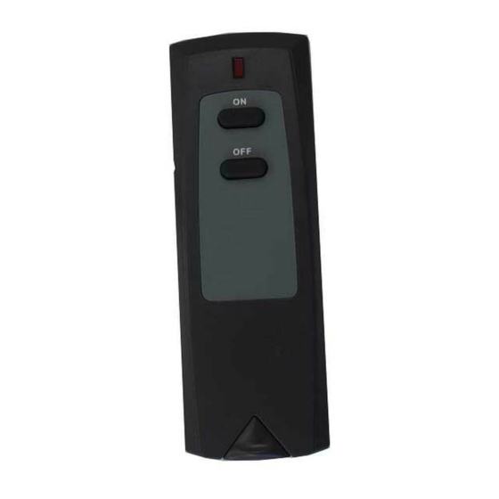
TRANSMITTER
SIGNAL
ON
LIGHT
OFF
ON/OFF
BUTTONS
ON
FRONT
OFF
Battery
3 Volt
Compartment
+
REMOTE RECEIVER
The remote receiver operates on (4) AA-size 1.5V batteries. It is recommended that ALKALINE batteries be used for longer battery life
and maximum microprocessor performance. IMPORTANT: New or fully charged batteries are essential for proper operation of the
remote receiver.
The remote receiver houses the microprocessor that responds to commands from the transmitter to control system operation. The
remote receiver has a 3-position slide switch for selecting the MODE of operation: OFF/REMOTE/ON
With the slide switch in the ON position the system will remain on until the slide
•
switch is placed in the OFF or REMOTE position.
With the slide switch in the REMOTE position (centered), the system will only operate
•
if the remote receiver receives commands from the transmitter.
With the slide switch in the OFF position the system is off.
•
It is suggested that the slide switch be placed in the off position if you will be
•
away from your home for an extended period of time. Placing the slide switch
in the OFF position also functions as a safety "lock-out" by both turning the system off and
OFF and rendering the remote receiver inoperative.
_________________________________________________________________________________________________________________________
Model: 4001 & RCKIT4001
900585-00 Rev. NC
Model: 4001& RCKIT4001
ATTEMPT TO INSTALL OR OPERATE
The transmitter has ON and OFF functions that are activated by pressing either
button on the face of the transmitter. When a button on the transmitter is
pressed, a signal light on the transmitter illuminates briefly to verify that a signal
has been sent. Upon initial use, there may be a delay of three seconds before
LABEL
the remote receiver will respond to the transmitter. This is part of the system's
design. If the signal light does not illuminate, check the position of the
transmitter's battery.
Code Switches
The transmitter has (2) code switches located on the back that will need to be set
when installation is complete. Note: Code setting section
A
O
C
M
E
K
G
I
1
15
3
13
5
11
7
9
The transmitter operates on (1) 3V Button Cell (Included) that powers the RF
BACK
signal. Before using the transmitter the 3-volt battery must be installed into the
battery compartments.
Remove the battery holder from the bottom of the transmitter insert the 3-volt
button cell battery in the battery holder with the plus (+) side up. Note the drawing
at the left.
It is recommended that a CR2032 lithium battery always be used for longer
Battery Life and maximum operational performance.
Requires 4-AA 1.5V
alkaline batteries
Slide
Switch
Remote Receiver
REV. 7-29-15
Page 1 of 4
Advertisement
Table of Contents

Related Manuals for IHP 4001


Summary of Contents for IHP 4001
- Page 1 OFF position also functions as a safety “lock-out” by both turning the system off and OFF and rendering the remote receiver inoperative. Remote Receiver _________________________________________________________________________________________________________________________ Model: 4001 & RCKIT4001 REV. 7-29-15 Page 1 of 4 900585-00 Rev. NC...
- Page 2 Make sure the remote receiver code switches have been set to match the transmitter code switches before completing the installation Note: Code setting section REMOTE NOTE: Black Slide Button is used for Hearth Mount applications. Remote Receiver _________________________________________________________________________________________________________________________ Model: 4001 & RCKIT4001 REV. 7-29-15 Page 2 of 4...
-
Page 3: Wiring Instructions
ON. The main gas flame should ignite. On Electronic ignition systems the spark electrode should begin sparking to ignite the pilot (the pilot may ignite after only one spark). After the pilot flame is lit, the main gas valve should open and the main gas flame should ignite. _________________________________________________________________________________________________________________________ Model: 4001 & RCKIT4001 REV. 7-29-15 Page 3 of 4... -
Page 4: General Information
If you cannot locate the dealer/distributor, then you must notify IHP in writing. IHP must be notified of the claimed defect in writing within 90 days of the date of failure. Notices should be directed to the IHP Warranty Department at 1508 Elm Hill Pike, Suite 108;...
Need help?
Do you have a question about the 4001 and is the answer not in the manual?
Questions and answers