Table of Contents
Advertisement
Quick Links
IF YOU CANNOT READ OR UNDERSTAND THESE INSTALLATION INSTRUCTIONS DO NOT ATTEMPT
INTRODUCTION
This remote control system was developed to provide a safe, reliable, and user-friendly remote control system for gas heating
appliances. The system can be operated thermostatically or manually from the transmitter. The system operates on radio frequencies
(RF) within a 20-foot range using non-directional signals. The system operates one of 1,048,576 security codes that are programmed
into the transmitter at the factory; the remote receiver's code must be matched to that of the transmitter prior to initial use.
Review COMMUNICATION SAFETY under the TRANSMITTER section. This safety feature provides an extra margin of safety when
The transmitter operates on (2) AAA size 1.5DCV batteries. It is recommended that ALKALINE batteries always be used
for longer battery life and maximum operational performance. IMPORTANT: New or fully charged batteries are essential
for proper operation of the multi-function transmitter. Insert (2) AAA size 1.5DCV batteries into the battery compartment
on the back of the transmitter, positioning the (+) and (-) ends of the batteries as indicated on the casing. When the
batteries are inserted, the screen in figure 2 (with similar numbers) will display.
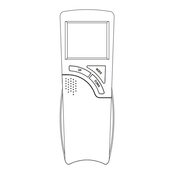
COVER CLOSED
Fig. 1 Transmitter Front and Back Views
LCD DISPLAY FUNCTIONS
1. BATTERY ICON - Symbol means battery power is low. Replace batteries within 2-weeks.
2. TIMER- Indicates time remaining before system shuts OFF, when timer-programmed; 9-hour maximum setting.
3. MODE- Indicates operation MODE of system. ON indicates the system is manually ON. When screens displays OFF
the entire system is turned OFF and THERMO indicates the system will automatically cycle ON/OFF, depending on
SET temperature.
4. SET- Indicates desire SET room temperature for THERMO operation.
5. FLAME – Indicates burner/valve are in the ON position .
6. CLOCK – Indicates the current time in AM/PM
7. ROOM – Indicates CURRENT room temperature.
8. °F indicates degrees Fahrenheit (°C indicates degrees Celsius).
IPH: RCL-S-STAT
Cat. No. H8861
INSTALLATION AND OPERATION INSTRUCTIONS
TO INSTALL OR OPERATE
the transmitter is out of normal 20-foot operating range.
+
-
SLIDE COVER
BACK OF
OPEN
TRANSMITTER
P/N 900257-00 Rev. A
Model: RCL-S-STAT
Note: If a LOW battery icon appears on the screen,
check the position of the batteries.
CAUTION: Due to the sensitive temperature-monitoring
components in the transmitter, it may be necessary to
allow the transmitter to stabilize to room temperature
before accurate room temperatures are displayed on
the screen. If the transmitter is activated from a
severe cold condition, it can take up to fifteen minutes
for accurate temperature readings to appear.
-
1
8
+
7
Fig. 2 LCD Display Functions
2
3
SET
ROOM
6
REV. 3-19-14 Page 1
4
5
Advertisement
Table of Contents

Subscribe to Our Youtube Channel
Related Manuals for IHP RCL-S-STAT


Summary of Contents for IHP RCL-S-STAT
- Page 1 Model: RCL-S-STAT Cat. No. H8861 INSTALLATION AND OPERATION INSTRUCTIONS IF YOU CANNOT READ OR UNDERSTAND THESE INSTALLATION INSTRUCTIONS DO NOT ATTEMPT TO INSTALL OR OPERATE INTRODUCTION This remote control system was developed to provide a safe, reliable, and user-friendly remote control system for gas heating appliances.
- Page 2 You may also press the ROOM SET button on the transmitter to stop the time digits from blinking and set the time. Fig. 9 Setting Minutes Fig. 8 Setting Hours P/N 900257-00 Rev. A IPH: RCL-S-STAT REV. 3-19-14 Page 2...
-
Page 3: Remote Receiver
The following wiring diagrams are for illustration purpose only. Follow instructions from manufacturer of gas valve and/ or electronic module for correct wiring procedures. Improper installation of electric components can cause damage to electronic module, gas valve and remote receiver. P/N 900257-00 Rev. A IPH: RCL-S-STAT REV. 3-19-14 Page 3... -
Page 4: Installation Instructions
(Rear View) Remote Receiver Fig.. 12. Wall plate to Receiver Receiver Slide Button Remote Receiver Plastic Switch Box Wall cover plate & Transmitter holder Fig. 13. Installing receiver into switch box. IPH: RCL-S-STAT P/N 900257-00 Rev. A REV. 3-19-14 Page 4... -
Page 5: Hearth Mount
1-2 minutes before trying again – this delay allows the microprocessor to reset its timer circuitry – and try up to two or three more times. Fig. 16 Learning IPH: RCL-S-STAT P/N 900257-00 Rev. A REV. 3-19-14 Page 5... -
Page 6: System Check
If the remote receiver is mounted out of children’s reach, placing the slide switch in the OFF position also functions as a safety “lock-out” by both turning the system off and rendering the remote receiver inoperative. IPH: RCL-S-STAT REV. 3-19-14 Page 6... - Page 7 MODE selected at the transmitter. The COMMUNICATION SAFETY feature will reactivate should the transmitter be taken out of the normal operating range or should the transmitter’s batteries fail or be removed. IPH: RCL-S-STAT P/N 900257-00 Rev. A REV. 3-19-14 Page 7...
- Page 8 Manually changing the SET temperature will activate the system in less than 10-seconds. If the “SWING” is changed, then a new room temperature differential will respond. Remember the Factory setting of the “SWING” temperature is 2º F. IPH: RCL-S-STAT P/N 900257-00 Rev. A REV. 3-19-14 Page 8...
- Page 9 MODE. Engaging the “LOCK-OUT” prevents only the manual operation of the TRANSMITTER. If in the auto modes, the THERMO operation will continue to operate normally. To totally “LOCK-OUT” the operation of the TRANSMITTER’S operating signals; the transmitter’s MODE must be set to OFF. P/N 900257-00 Rev. A IPH: RCL-S-STAT REV. 3-19-14 Page 9...
-
Page 10: Fcc Requirements
If you cannot locate the dealer/distributor, then you must notify IHP in writing. IHP must be notified of the claimed defect in writing within 90 days of the date of failure. Notices should be directed to the IHP Warranty Department at 1508 Elm Hill Pike, Suite 108;...
Need help?
Do you have a question about the RCL-S-STAT and is the answer not in the manual?
Questions and answers