
Related Manuals for Measurement Computing CIO-DAS16/M1/16


Summary of Contents for Measurement Computing CIO-DAS16/M1/16
- Page 1 CIO-DAS16/M1/16 High Speed Analog Inputs & Digital I/O User’s Guide Revision 4 November, 2000...
- Page 2 When that happens, just return the board with an order for its replacement at only 50% of the list price. Measurement Computing Corp. does not need to profit from your misfortune. By the way, we will honor this warranty for any other manufacture’s board that we have a replacement for! 30 DAY MONEY-BACK GUARANTEE Any Measurement Computing Corp.
-
Page 3: Table Of Contents
Table of Contents 1 INTRODUCTION ..............2 INSTALLATION . - Page 4 This page is blank.
-
Page 5: Introduction
1 INTRODUCTION CIO-DAS16/M1/16 sets the standard for high speed, 16-bit data acquisition boards for ISA bus compatible computers. The board provides 8 fully differential input channels with a variety of software programmable input ranges. The board will transfer a full 1 million samples per second to Measurement Computing’s MEGA-FIFO memory board, and directly over the ISA bus when used in high speed (200 MHz+) Pentium™... -
Page 6: Signal Connections
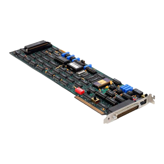
3 SIGNAL CONNECTIONS There are two connectors on the CIO-DAS16/M1/16. The 37-pin connector which extends through the mounting plate and extends out the rear of the PC is primarily for analog signals, and is referred to as the analog connector. The 40-pin header connector at the rear of the board carries the 24 digital I/O and is referred to as the digital connector. -
Page 7: Analog Inputs
Close attention must be paid to how analog signals are connected to the board. The CIO-DAS16/M1/16 has eight differential analog input channels. Each channel has a signal high input and a signal low input. The measurement made by the A/D is the voltage difference between the LOW and HIGH inputs. -
Page 8: Floating Signals
LLGND). Examples are a battery, an isolated precision power supply or a sensor which is not earth grounded. A reference between signal LOW and LLGND must be provided because the CIO-DAS16/M1/16 inputs are differential. Failure to supply the reference resistor (10K) will result in unrepeatable readings (Figure 3-3). -
Page 9: Avoid Ground Loops
LSTTL (Low power Schotky TTL). If you desire to control or sense any device other than TTL IC chips, please use appropriate signal conditioning, such as solid state relays or electromechanical relays. See the Measurement Computing catalog for SSR-RACK24 and CIO-ERB24 interface accessories. -
Page 10: Digital I/O Connector
3.6.1 DT-CONNECT IN MASTER MODE ONLY The CIO-DAS16/M1/16 implements DT-Connect MASTER MODE only. DT-Connect is always enabled and is never busy. The ENABLED and BUSY signal levels are fixed in hardware. Since DT-Connect is always enabled, any A/D conversions are always transferred out the DT-Connect regardless of the bus transfer method specified. The CIO-DAS16/M1/16 can only operate in DT-Connect schemes where it is the sole master. - Page 11 DT-Connect to store data on a memory board. Please see the data sheet on the MEGA-FIFO, Measurement Computing’s 128 million sample buffer board as an example of a DT-Connect...
-
Page 12: Software
4 SOFTWARE There are three common methods for generating software for the CIO-DAS16/M1/16. These are: Writing custom software using our Universal Library package, using a fully integrated software package (e.g. SoftWIRE), or doing direct, register-level programming. 4.1 CUSTOM SOFTWARE UTILIZING THE UNIVERSAL LIBRARY Many users write custom software using Universal Library. -
Page 13: Register Map
5 REGISTER MAP 5.1 DAS16/M1/16 REGISTER MAP Table 5-1. DAS16/M1/16 Register Descriptions ADDRESS READ FUNCTION WRITE FUNCTION BASE A/D Data - 16 bits Software Start A/D Conversion BASE + 1 Not Used Not Used BASE + 2 Channel Mux Set Channel Mux read/Reset FIFO BASE + 3 ID, Digital In 0 to 3, External Control... -
Page 14: Channel Mux Hi/Lo Limits Word Register
READ On read, the 16-bit ADC value is presented in 'left-justified' format, with the most-significant ADC bit at position #15; the least significant ADC bit at position #0 of the data word. WRITE A write to the base address causes an A/D conversion, (Bits “0” and “1” of BASE+9 must be “0”.) Also, the write to base address acts as an Internal Trigger to start conversions if the method of converting is External or Internal Pacer. -
Page 15: Status Register
WRITE Not Used Not Used Not Used Not Used All of the four bits are latched TTL outputs. The WRITE to this register also clears external trigger latched bit. 5.5 STATUS REGISTER BASE ADDRESS + 8 Example, 308h, 776 Decimal READ OVRN INTB... - Page 16 INT4:1 - Interrupt selection Table 5-2. Interrupt Coding INT8 INT4 INT2 INT1 INTERRUPT DISABLED Not Available Not Available Not Available Not Available BMDE - Burst Mode Enable. 0 = disable, 1 = enabled. The number of channels in the burst are set in BASE +Ah register.
-
Page 17: Burst Length, External Trigger, Ctr0/Trg0
5.7 BURST LENGTH, EXTERNAL TRIGGER, CTR0/TRG0 BASE ADDRESS +Ah Example, 30Ah, 778 Decimal READ/WRITE TRGPOL TRGSEL CTR0 TRG0 BL3:0 - Burst Length. The number of channels in the burst are set by BL3:0, where the channels that are contained in the burst are set by register BASE+2. For example: To do a channel burst conversion on channels 0 to 2, set BASE +2 to 20 hex and the upper nibble of BASE +Ah to 3. -
Page 18: 8254 Data And Control Registers
RCG - Residual Counter Gate. 0 = disabled, 1 = enabled. The Residual Counter Gate gates Counter 0 'on' to allow the software to count the residual number of samples taken off the FIFO in REP INSW mode. FFNE - FIFO Not Empty. 0 = FIFO is not empty - contains A/D data, 1 = FIFO is empty. UNI/BIP - A/D input Unipolar/Bipolar mode select. -
Page 19: 82C55 Digital I/O Data And Control Registers
6.9.4 8254 CONTROL REGISTER BASE + Fh Example, 30Fh, 783 decimal WRITE ONLY The control register is used to set the operating Modes of 8254 Counters 0, 1, and 2. A counter is configured by writing the correct Mode information to the Control Register, then the proper count data must be written to the specific Counter Register. -
Page 20: Calibration And Test
, calibration routine. The CIO-DAS16/M1/16 should be calibrated for the range you intend to use it in. When the range is changed, slight variations in zero and full scale may result. These variations can be measured and removed in software if necessary. -
Page 21: Specifications
7 SPECIFICATIONS Analog input section A/D converter type Datel ADS-30356 Subranging Resolution 16 bits Programmable ranges ±5V, ±2.5V, ±1.25V, ±.625V, 0 to 10V, 0 to 5V, 0 to 2.5V, 0 to 1.25V A/D pacing Programmable: internal counter or external source (Din0, rising edge) or software polled Burst mode intersample time 1 µs... - Page 22 Input High 2.0 volts min, 5.5 volts absolute max 0.8 volts max, −0.5 volts absolute min Input Low Interrupts Programmable levels 2 to 7, 10 to12, 14, 15; Positive-edge triggered Interrupt enable Programmable Interrupt sources A/D End-of-conversion, A/D FIFO half full, A/D Residual Counter Counter section Counter type 82C54...
- Page 23 Environmental Operating temperature range 0 to 60°C −40 to 100°C Storage temperature range Humidity 0 to 90% non-condensing Power consumption +5V: Operating 2.25 A typical / 2.9 A maximum All Specifications typical for 25 DegC unless otherwise specified.
- Page 24 For your notes.
- Page 25 EC Declaration of Conformity We, Measurement Computing Corp., declare under sole responsibility that the product: CIO-DAS16/M1/16 High speed analog input board and Digital I/O Part Number Description to which this declaration relates, meets the essential requirements, is in conformity with, and CE marking has been applied...
- Page 26 Measurement Computing Corporation 16 Commerce Boulevard, Middleboro, MA 02346 (508) 946-5100 Fax: (508) 946-9500 E-mail: info@measurementcomputing.com www. measurementcomputing.com...
Need help?
Do you have a question about the CIO-DAS16/M1/16 and is the answer not in the manual?
Questions and answers