
Subscribe to Our Youtube Channel
Summary of Contents for REXROTH IndraControl VDP 16.3
- Page 1 Electric Drives Linear Motion and and Controls Hydraulics Assembly Technologies Pneumatics Service Rexroth IndraControl R911336378 Edition 03 VDP 16.3, VDP 40.3, VDP 60.3 Operator Display Operating Instructions...
- Page 2 © Bosch Rexroth AG 2014 This document, as well as the data, specifications and other information set forth in it, are the exclusive property of Bosch Rexroth AG. It may not be repro- duced or given to third parties without its consent.
-
Page 3: Table Of Contents
VDP 16.3, VDP 40.3, VDP 60.3 Bosch Rexroth AG Table of Contents Table of Contents Page About this Documentation..............1 Product Identification and Scope of Delivery........2 Product Identification................2 Scope of Delivery................... 3 Using the Safety Instructions..............3 Safety Instructions – Structure.............. 3 Explaining Signal Words and Safety Alert Symbol......... - Page 4 XSER Interfaces and XVID Interfaces........... 16 Assembly, Disassembly and Electrical Installation......16 10.1 Installation Notes................. 16 10.2 Housing Dimensions................17 10.2.1 IndraControl VDP 16.3................. 17 10.2.2 IndraControl VDP 40.3................. 20 10.2.3 IndraControl VDP 60.3................. 23 10.3 Mounting Cut-out................. 25 10.4 Mounting Dimensions VDP 16.3............
- Page 5 VDP 16.3, VDP 40.3, VDP 60.3 Bosch Rexroth AG Table of Contents Page 14.3.2 Backlight Switch-Off................43 14.4 Cleaning Notes..................44 14.5 Regular Maintenance Tasks..............44 Ordering Information................44 15.1 Accessories and Spare Parts............... 44 15.2 VDP 16.3....................45 15.3 VDP 40.3....................
- Page 6 Bosch Rexroth AG VDP 16.3, VDP 40.3, VDP 60.3 DOK-SUPPL*-VDP*XX.3***-IT03-EN-P...
-
Page 7: About This Documentation
VDP 16.3, VDP 40.3, VDP 60.3 Bosch Rexroth AG About this Documentation 1 About this Documentation Overview – target groups and product phases The activities, product phases and target groups that refer to the present docu- mentation are marked in red color in the following figure. -
Page 8: Product Identification And Scope Of Delivery
Please email your feedback on the documentations to Feed- back.Documentation@boschrexroth.de. Directly insert comments in the elec- tronic PDF document and send the PDF file to Bosch Rexroth. 2 Product Identification and Scope of Delivery 2.1 Product Identification The type plate is located on the rear panel. -
Page 9: Scope Of Delivery
IN 3AC 230V 50760Hz : AC 230V / 115V OUT 10/7,5/5/5/1,5/1,5A max. : 0,7A / 1,4A SN: 004012652 I-C-B-T-V I-C-B-H-T-V IND.CONT-EQ 17YB Bosch Rexroth Electric Drives and Controls GmbH SW-Version V0,002 XXXXXXXXXXXXXXXXX D-6471 1 Erbach Made in Germany IND.CONT.EQ 17YB 123456814... -
Page 10: Explaining Signal Words And Safety Alert Symbol
Bosch Rexroth AG VDP 16.3, VDP 40.3, VDP 60.3 Using the Safety Instructions Consequences and Safety alert symbol source of danger Signal word Burns and chemical burns due to wrong CAUTION battery treatment! Do not open the batteries and do not heat them over 80 °C. -
Page 11: Symbols Used
Tips are displayed as follows: This is a tip. 4 Intended Use The Bosch Rexroth operator terminals are passive operation and visualization terminals. They form a PC-based operator terminal when used with a Bosch Rexroth control cabinet PC. Danger of destruction of the device if not ex-... -
Page 12: Spare Parts, Accessories And Wear Parts
Bosch Rexroth AG VDP 16.3, VDP 40.3, VDP 60.3 Spare Parts, Accessories and Wear Parts Risk of destroying the touch screen or the front NOTICE panel by using inappropriate items. Operate the touch screen only with your finger or with a special touch pen (parts number 1070923266). -
Page 13: Connecting Cables For The Usb Interface
VDP 16.3, VDP 40.3, VDP 60.3 Bosch Rexroth AG Spare Parts, Accessories and Wear Parts Ordering code Part number Description RKB0008/010,0 (*******-*******-*******) R911170153 Length 10 m RKB0008/015,0 (*******-*******-*******) R911171183 Length 15 m RKB0008/020,0 (*******-*******-*******) R911171184 Length 20 m RKB0008/025,0 (*******-*******-*******) -
Page 14: Wear Parts
Bosch Rexroth AG VDP 16.3, VDP 40.3, VDP 60.3 Ambient Conditions Ordering code Part number Description RKB0050/001,0 R911172944 USB connecting cable with increased noise immunity; length 1 m RKB0050/003,0 R911172945 USB connecting cable with increased noise immunity; length 3 m Tab. -
Page 15: Technical Data
VDP 16.3, VDP 40.3, VDP 60.3 Bosch Rexroth AG Technical Data In operation Transport Storage Mechanical strength Max. vibration: Max. shock: Max. shock: Frequency range: 10 Hz 15 g 11 ms 15 g 11 ms to 150 Hz acc. to EN 60068-2-27, acc. - Page 16 Bosch Rexroth AG VDP 16.3, VDP 40.3, VDP 60.3 Technical Data VDP 40.3DE VDP 40.3BI VDP 40.3DF Display 381 mm TFT (15"), 1024 x 768 pixels, 16.7 million colors Surface − front panel Color RAL 7035 Light gray Operation Touch screen operation Key operation...
-
Page 17: Standards
VDP 16.3, VDP 40.3, VDP 60.3 Bosch Rexroth AG Standards VDP 40.3DI VDP 40.3AL Per USB port max. 500 mA, total current at all USB ports is max. 1 A Weight 5.8 kg Tab. 7-3: Technical data of the VDP 40.3 (DI, AL) VDP 60.3FE... -
Page 18: Ce Marking
Bosch Rexroth AG VDP 16.3, VDP 40.3, VDP 60.3 Standards Standard Meaning EN 60,068-2-6 Vibration test EN 60,068-2-27 Shock test EN 60 721-3-1 and Climatic class EN 60,721-3-3 Tab. 8-1: Used Standards 8.2 CE Marking 8.2.1 Declaration of Conformity The electronic products that are described in the present instructions, comply... -
Page 19: Interfaces
VDP 16.3, VDP 40.3, VDP 60.3 Bosch Rexroth AG Interfaces UL file no. E210730 However, there can be combinations or extension stages with limited or missing certification. Thus, verify the registration according to the UL marking on the de- vice. -
Page 20: Dc 24 V Voltage Supply
Bosch Rexroth AG VDP 16.3, VDP 40.3, VDP 60.3 Interfaces Designation at Connection type Connector type, integra- Mating connector or ca- the housing ble (from outside) XUSBIN USB2.0 connection to the control USB female connector, USB connector, cabinet PC. Length 5 m max. -
Page 21: S1 Dip Switch
VDP 16.3, VDP 40.3, VDP 60.3 Bosch Rexroth AG Interfaces 9.4 S1 DIP Switch 9.4.1 Overview Fig. 9-3: S1 DIP switch on the connector panel of the operating display Designation at the Switch type Function housing S1/1 DIP switch No function... -
Page 22: Xser Interfaces And Xvid Interfaces
Bosch Rexroth AG VDP 16.3, VDP 40.3, VDP 60.3 Assembly, Disassembly and Electrical Installation Connect only USB devices that meet the USB specification. The VDP power supply switches off if the total NOTICE current of all USB connectors exceeds 1 A. -
Page 23: Housing Dimensions
Bosch Rexroth AG Assembly, Disassembly and Electrical Installation 10.2 Housing Dimensions 10.2.1 IndraControl VDP 16.3 VDP 16.3 standard version Irrespective of the design of the VDP 16.3 standard variants with keys (M-keys) or touch screen the front panel width is 350 mm and the height is 290 mm. All values in the illustrations are given in mm. - Page 24 Bosch Rexroth AG VDP 16.3, VDP 40.3, VDP 60.3 Assembly, Disassembly and Electrical Installation Fig. 10-2: VDP 16.3BK: Top View Fig. 10-3: VDP 16.3BK: Left view VDP 16.3AK customized version The front panel width of the VDP 16.3AK is 360 mm and the height is 300 mm. It has no USB connection.
- Page 25 VDP 16.3, VDP 40.3, VDP 60.3 Bosch Rexroth AG Assembly, Disassembly and Electrical Installation 55.5 Fig. 10-4: Dimensions: Front panel of the VDP 16.3AK 12.5 167.5 167.5 Fig. 10-5: VDP 16.3AK: Top View 19/53 DOK-SUPPL*-VDP*XX.3***-IT03-EN-P...
-
Page 26: Indracontrol Vdp 40.3
Bosch Rexroth AG VDP 16.3, VDP 40.3, VDP 60.3 Assembly, Disassembly and Electrical Installation 137.5 12.5 137.5 Fig. 10-6: VDP 16.3AK: Left view VDP 16.3BK + DB VDP 16.3AK Width 350 mm 360 mm Height 290 mm 300 mm Mounting depth 41 mm Tab. - Page 27 VDP 16.3, VDP 40.3, VDP 60.3 Bosch Rexroth AG Assembly, Disassembly and Electrical Installation Fig. 10-7: Dimensions: Front panel of the VDP 40.3BI devices The front panels of the VDP 40.2DE, -BI, -DF and VDP 40.3DG have the same di- mensions.
- Page 28 Bosch Rexroth AG VDP 16.3, VDP 40.3, VDP 60.3 Assembly, Disassembly and Electrical Installation Fig. 10-9: VDP 40.3BI and VDP 40.3DE: Left view VDP 40.3AL customized version The front panel width of the VDP 40.3AL is 417 mm and the height is 380 mm. It has no USB connection.
-
Page 29: Indracontrol Vdp 60.3
VDP 16.3, VDP 40.3, VDP 60.3 Bosch Rexroth AG Assembly, Disassembly and Electrical Installation 12.5 Fig. 10-11: VDP 40.3AL: Top View 12.5 177.5 177.5 Fig. 10-12: VDP 40.3AL: Left view VDP 40.3DE + BI + DF +DG VDP 40.3AL Width... - Page 30 Bosch Rexroth AG VDP 16.3, VDP 40.3, VDP 60.3 Assembly, Disassembly and Electrical Installation IndraControl V Fig. 10-13: Dimensions: Front panel of the VDP 60.3 Fig. 10-14: VDP 60.3: Top View 24/53 DOK-SUPPL*-VDP*XX.3***-IT03-EN-P...
-
Page 31: Mounting Cut-Out
VDP 16.3, VDP 40.3, VDP 60.3 Bosch Rexroth AG Assembly, Disassembly and Electrical Installation Fig. 10-15: VDP 60.3: Left view 10.3 Mounting Cut-out Mount the operating display as follows: Loss of degree of protection IP 65! The housing in which the operator display is installed, has to fulfil... - Page 32 Bosch Rexroth AG VDP 16.3, VDP 40.3, VDP 60.3 Assembly, Disassembly and Electrical Installation ① Mounting bolt Fig. 10-16: Position of the mounting bolts Damage of the mechanics caused by wrong NOTICE tightening torque. Tighten the screws and nuts with the corresponding torque according to the fol- lowing table.
-
Page 33: Mounting Dimensions Vdp 16.3
VDP 16.3, VDP 40.3, VDP 60.3 Bosch Rexroth AG Assembly, Disassembly and Electrical Installation Threads Mounting torques 1.4 Nm 2.8 Nm Tab. 10-3: Mounting torques 10.4 Mounting Dimensions VDP 16.3 167.5 167.5 ① Drilled hole for the mounting bolts, bore diameter 5 mm ②... -
Page 34: Mounting Dimensions Vdp 40.3
Bosch Rexroth AG VDP 16.3, VDP 40.3, VDP 60.3 Assembly, Disassembly and Electrical Installation 10.5 Mounting Dimensions VDP 40.3 ① Drilled hole for the mounting bolts, bore diameter 5 mm ② Mounting cut-out Fig. 10-18: Mounting dimensions of the VDP 40.3 devices (in millimetres) 28/53 DOK-SUPPL*-VDP*XX.3***-IT03-EN-P... -
Page 35: Mounting Dimensions Vdp 60.3
VDP 16.3, VDP 40.3, VDP 60.3 Bosch Rexroth AG Assembly, Disassembly and Electrical Installation 10.6 Mounting Dimensions VDP 60.3 231.5 231.5 ① Drilled hole for the mounting bolts, bore diameter 5 mm ② Mounting cut-out Fig. 10-19: Mounting dimensions of the VDP 60.3 devices (in millimetres) 10.7 Disassembly... -
Page 36: Electrical Wiring
Bosch Rexroth AG VDP 16.3, VDP 40.3, VDP 60.3 Assembly, Disassembly and Electrical Installation 10.8 Electrical Wiring 10.8.1 Wiring Wiring 230 V Min. 16 mm ² ( green/yellow) To the housing of the control cabinet Leads 16 mm ² (green/yellow) To the device 6 mm²... - Page 37 VDP 16.3, VDP 40.3, VDP 60.3 Bosch Rexroth AG Assembly, Disassembly and Electrical Installation Danger to life and risk of injury caused by con- DANGER nection of power supply units, which cause pro- tective extra-low voltage (e.g. +24 V), to supply voltages, for which they are not designed.
- Page 38 Bosch Rexroth AG VDP 16.3, VDP 40.3, VDP 60.3 Assembly, Disassembly and Electrical Installation High electrical voltage! Danger to life and risk of DANGER injury caused by electric shock or bodily harm caused by supply voltage on the protective ex- tra-low voltage (e.g.
- Page 39 VDP 16.3, VDP 40.3, VDP 60.3 Bosch Rexroth AG Assembly, Disassembly and Electrical Installation Control cabinet PC and display to UPS Overvoltage category I Control cabinet PC Terminal block UK6-FSI/6 VSB 40.3 with automatic cut-out TCP 10 A (PHOENIX CONTACT) is recommended VSP xx.3...
-
Page 40: Connecting The Control Cabinet Pc To Operating Display
Bosch Rexroth AG VDP 16.3, VDP 40.3, VDP 60.3 Assembly, Disassembly and Electrical Installation 10.8.2 Connecting the Control Cabinet PC to Operating Display Connection diagram Violet XSER XSER Operator display Control cabinet PC XVID XVID Black Functional earth ground Fig. 10-24: Wiring the operating display to the control cabinet PC Connection 1. - Page 41 VDP 16.3, VDP 40.3, VDP 60.3 Bosch Rexroth AG Assembly, Disassembly and Electrical Installation When installing CDI cables with a diameter of 7.4 mm observe the bending radius: Radius (when bended once during installation): 4 × cable diame- ● Minimum bending radius (when moved permanently): 8 × cable ●...
-
Page 42: Connecting The Operating Display To The 24 V Voltage Supply
Bosch Rexroth AG VDP 16.3, VDP 40.3, VDP 60.3 Assembly, Disassembly and Electrical Installation 10.8.3 Connecting the Operating Display to the 24 V Voltage Supply Connection diagram 24 V voltage X1S1 Potential-free supply industrial power supply Operator display unit acc. to DIN EN 60742, classification VDE 0551 Fig. -
Page 43: Connection Scheme - Power Supply Unit, Ups, Control Cabinet Pc And Operating Display
VDP 16.3, VDP 40.3, VDP 60.3 Bosch Rexroth AG Commissioning 10.8.4 Connection Scheme – Power Supply Unit, UPS, Control Cabinet PC and Operating Display USB cable USB connection USB connection for USB2.0, max. 5 m Type A Type B XUSB1..6... -
Page 44: Device Description
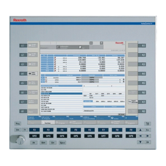
Bosch Rexroth AG VDP 16.3, VDP 40.3, VDP 60.3 Device Description 12 Device Description 12.1 General Information ① ④ Status displays Operating keys OP2 to OP9 ② ⑤ Machine function keys (M-keys) L1 to L8 M-keys R1 to R8 ③... -
Page 45: Vdp 16.3 Keys And Vdp 40.3 Keys
VDP 16.3, VDP 40.3, VDP 60.3 Bosch Rexroth AG Device Description 12.2.2 VDP 16.3 Keys and VDP 40.3 Keys Function and operating keys (F... + OP...) The assignment of the function and operating keys (F... + OP...) is determined by the respective application software. -
Page 46: Operating And Error Displays
Bosch Rexroth AG VDP 16.3, VDP 40.3, VDP 60.3 Device Description Key at the VDP 16.3, VDP 40.3 Key codes if UpperClassFilter is Key codes if UpperClassFilter is activated deactivated <CTRL> + <ALT> + <SHIFT <F13> to <F20> LEFT> + <1 to 8> (not on nu- meric block) <CTRL>... -
Page 47: Y-Repeater
Two operator displays can be connected to one control cabinet PC using a Y-re- peater. It cascades up to four operator displays. For more information about the Y-Repeater, refer to the operating instructions "Rexroth IndraControl VAC 01 Y- Repeater" (see tab. -
Page 48: Maintenance
Bosch Rexroth AG VDP 16.3, VDP 40.3, VDP 60.3 Maintenance The USB flash drive does not function, Set the DIP switch on the VDP to <30 m ● although other USB devices function USB devices and touch screen do not Set the DIP switch adequately to the cable length ●... -
Page 49: Backlight Switch-Off
VDP 16.3, VDP 40.3, VDP 60.3 Bosch Rexroth AG Maintenance 14.3.2 Backlight Switch-Off To extend the service life of the LCD backlight, the flat screen display is provi- ded with a backlight switch-off. This function "darkens" the display when the panel PC has been not operated for a certain period of time. -
Page 50: Cleaning Notes
Bosch Rexroth AG VDP 16.3, VDP 40.3, VDP 60.3 Ordering Information 14.4 Cleaning Notes The surface of the membrane as well as the dis- NOTICE play seal are dissolved by solvents! Do not use any solvents (e. g. diluents)! ●... -
Page 51: Vdp 16.3
VDP 16.3, VDP 40.3, VDP 60.3 Bosch Rexroth AG Ordering Information 15.2 VDP 16.3 Abbrev. column 1 2 3 4 6 7 8 9 1 2 3 4 6 7 8 9 Example: V D P 1 6 . 3 D B N - D 1 - N N - N N Product VDP. -
Page 52: Vdp 40.3
Bosch Rexroth AG VDP 16.3, VDP 40.3, VDP 60.3 Ordering Information 15.3 VDP 40.3 Abbrev. column 1 2 3 4 6 7 8 9 1 2 3 4 6 7 8 9 Example: V D P 4 0 . 3 D E N - D 1 - N N - N N Product VDP. -
Page 53: Vdp 60.3
VDP 16.3, VDP 40.3, VDP 60.3 Bosch Rexroth AG Disposal 15.4 VDP 60.3 Abbrev. Column 1 2 3 4 6 7 8 9 1 2 3 4 6 7 8 9 Example: V D P 6 0 . 3 F E N - D 1 - N N - N N Product VDP. -
Page 54: Packaging
Bosch Rexroth AG VDP 16.3, VDP 40.3, VDP 60.3 Service and Support Send the products "free domicile" to the following address: Bosch Rexroth AG Electric Drives and Controls Bürgermeister-Dr.-Nebel-Straße 2 D-97816 Lohr am Main, Germany 16.2 Packaging The packaging materials consist of cardboard, plastic material, wood or expan- ded polystyrene (EPS). -
Page 55: Index
VDP 16.3, VDP 40.3, VDP 60.3 Bosch Rexroth AG Index Index Accessories........6 Electrical wiring......30 Ambient conditions......8 Error causes........41 Assembly........16 External 24 V power supply unit..6 Backlight........8, 43 Feedback........2 Backlight switch-off...... 43 Function and Operating Keys Bending radius...... - Page 56 Bosch Rexroth AG VDP 16.3, VDP 40.3, VDP 60.3 Index Pin assignment Wear parts........6 XUSB........15 Wiring 230 V......... 30 Product identification..... 2 Wiring 400 V......... 31 S1 DIP switch....... 15 XUSB interfaces......15 Safety alert symbol......4 Safety instructions...... 3, 4 Scope of delivery......
- Page 57 VDP 16.3, VDP 40.3, VDP 60.3 Bosch Rexroth AG 51/53 DOK-SUPPL*-VDP*XX.3***-IT03-EN-P...
- Page 58 Bosch Rexroth AG VDP 16.3, VDP 40.3, VDP 60.3 52/53 DOK-SUPPL*-VDP*XX.3***-IT03-EN-P...
- Page 59 VDP 16.3, VDP 40.3, VDP 60.3 Bosch Rexroth AG Notes...
- Page 60 Bosch Rexroth AG Electric Drives and Controls P.O. Box 13 57 97803 Lohr, Germany Bgm.-Dr.-Nebel-Str. 2 97816 Lohr, Germany Tel. +49 9352 18 0 +49 9352 18 8400 www.boschrexroth.com/electrics DOK-SUPPL*-VDP*XX.3***-IT03-EN-P...
Need help?
Do you have a question about the IndraControl VDP 16.3 and is the answer not in the manual?
Questions and answers