Emerson Fisher 299H Installation Manual
Fisher 299h series
Hide thumbs
Also See for Fisher 299H:
- Instruction manual (21 pages) ,
- Installation manual (9 pages) ,
- Manual (19 pages)
Table of Contents
Advertisement
Quick Links
Installation Guide
English – September 2012
Introduction
This Installation Guide provides instructions for
installation, startup, and adjustment of 299H Series
regulators. To receive a copy of the Instruction
Manual, contact your local Sales Office or view
a copy at www.fisherregulators.com. For further
information refer to: 299H Series Instruction
Manual, form 5497, D102684X012.
P.E.D. Categories
This product may be used as a safety accessory
with pressure equipment in the following Pressure
Equipment Directive 97/23/EC categories. It may
also be used outside of the Pressure Equipment
Directive using sound engineering practice (SEP)
per table below.
product size
DN 40, 50 / NPS 1-1/2, 2
Specifications
Available Configurations
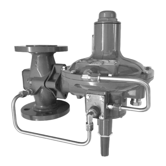
Type 299H: Pilot-operated pressure reducing
regulator with a pilot integrally mounted to the
actuator casing
Type 299HR: A Type 299H with a token internal
relief valve to relieve minor overpressure caused
by thermal expansion
Type 299HS: Same as the Type 299H
with a Type VSX-2 slam-shut valve which
provides overpressure or overpressure and
underpressure protection
Type 299HSR: Same as the Type 299HS with
an internal token relief valve
Body Size and End Connection Styles
See Table 1
Maximum Operating Inlet Pressure
by Orifice Size
6.4 x 9.5 mm / 1/4 x 3/8 inch – 12.1 bar / 175 psig
9.5 mm / 3/8 inch – 12.1 bar / 175 psig
13 mm / 1/2 inch – 12.1 bar / 175 psig
19 mm / 3/4 inch – 10.3 bar / 150 psig
22 mm / 7/8 inch
– 8.6 bar / 125 psig
(3)
25 mm / 1 inch
– 6.9 bar / 100 psig
(3)
30 mm / 1-3/16 inch
1. The pressure/temperature limits in this Installation Guide and any applicable
standard or code limitation should not be exceeded.
2. For optimum performance, a pilot supply regulator may be installed in the pilot
supply tubing between the main valve and pilot.
3. This orifice size is not available for Types 299HS and 299HSR.
category
fluid type
I
1
(1)
– 5.5 bar / 80 psig
(3)
www.fisherregulators.com
Maximum Casing and Emergency
Outlet Pressure
(1)
4.5 bar / 66 psig
Proof Test Pressure
All Pressure Retaining Components have been
proof tested per Directive 97/23/EC - Annex 1,
Section 7.4
Outlet (Control) Pressure Ranges
See Table 2
Minimum Differential Pressure For Full Stroke
0.10 bar / 1.5 psi
Maximum Set Pressure for Type 299HS
1.1 bar / 16 psig
Maximum Set Pressure for Type VSX-2
Slam-Shut Device
(1)
1.6 bar / 23 psig
Minimum and Maximum Trip Pressure Ranges
See Table 3
Temperature Capabilities
-29 to 66°C / -20 to 150°F
Installation
!
Only qualified personnel should
install or service a regulator.
Regulators should be installed,
operated, and maintained in
accordance with international and
applicable codes and regulations,
and Emerson Process Management
Regulator Technologies Inc. (Regulator
Technologies) instructions.
If the regulator vents fluid or a leak
develops in the system, it indicates that
service is required. Failure to take the
regulator out of service immediately
may create a hazardous condition.
Personal injury, equipment damage,
or leakage due to escaping fluid
or bursting of pressure-containing
parts may result if this regulator is
overpressured or is installed where
service conditions could exceed the
limits given in the Specifications
section, or where conditions exceed
any ratings of the adjacent piping or
piping connections.
299H Series
(1)(2)
(1)
(1)
Warning
(1)
Advertisement
Table of Contents

Subscribe to Our Youtube Channel
Related Manuals for Emerson Fisher 299H


Summary of Contents for Emerson Fisher 299H
- Page 1 Type 299HSR: Same as the Type 299HS with applicable codes and regulations, an internal token relief valve and Emerson Process Management Regulator Technologies Inc. (Regulator Body Size and End Connection Styles Technologies) instructions. See Table 1...
- Page 2 299H Series Overpressure Protection To avoid such injury or damage, provide pressure-relieving or pressure- The recommended pressure limitations are limiting devices (as required by stamped on the regulator nameplate. Some type the appropriate code, regulation, of overpressure protection is needed if the actual or standard) to prevent service inlet pressure exceeds the maximum operating conditions from exceeding limits.
- Page 3 299H Series Table 1. Body Sizes and End Connection Styles Body size Body Material and end connection style Cast Iron Steel Inch Ductile Iron (For Types 299H and 299HR only) (For Types 299H and 299HR only) 1-1/4 - - - - - - - - 1-1/2 NPT, CL125 FF, CL250 RF, and...
- Page 4 299H Series 299H Series Regulator To adjust the Underpressure Trip Spring: (Figures 3 through 6) (continued) 1. Adjust the underpressure trip spring back to its minimum compression. Description 2. Backpressure the unit with the desired Adjustment Nut Closing Spring underpressure trip pressure. Pressure Equalization Spring Diaphragm 3.
- Page 5 299H Series VIEW A VIEW A T80423 VIEW A NOTE: FOR KEYS 82 AND 83, REFER TO 299H SERIES REGULATORS PARTS LIST. Figure 1. Type VSX-2 Assembly A7008 Figure 2. Optional P590 Series Filter...
- Page 6 299H Series T80391-6 TYPE 299H PILOT WITHOUT RELIEF VALVE T80391-6 TYPE 299HR PILOT WITH TOKEN RELIEF VALVE Figure 3. 299H Series Pilot Assemblies T80391-2 T80391-4 T80391-3 EXTERNAL REGISTRATION dual registration internal registration Figure 4. 299H Series Registration Assemblies...
- Page 7 299H Series T80391 see figure 4 T80391-7 299H SERIES PILOT TRIM Figure 5. 299H Series Interior Assembly...
- Page 8 For further information visit www.emersonprocess.com/regulators The Emerson logo is a trademark and service mark of Emerson Electric Co. All other marks are the property of their prospective owners. Fisher is a mark owned by Fisher Controls International LLC, a business of Emerson Process Management.
Need help?
Do you have a question about the Fisher 299H and is the answer not in the manual?
Questions and answers