Table of Contents
Advertisement
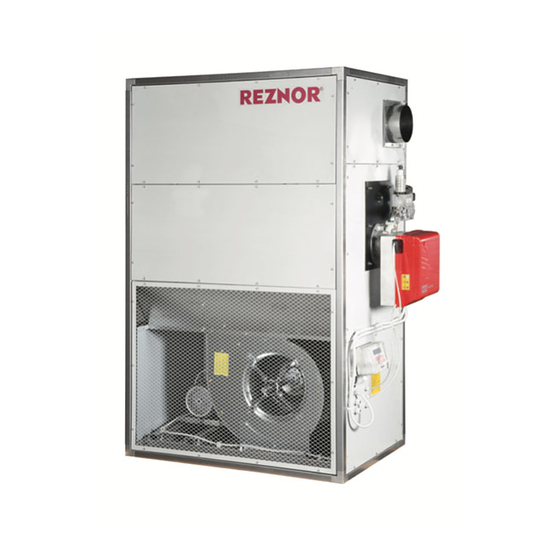
Installation & Operating Manual
Floor-Standing
Warm Air Heater
FSE Model Range (Gas & Oil)
Warnings
Nortek Global HVAC equipment must be installed and
maintained in accordance with the requirements of the
Codes of Practice or rules in force.
All external wiring must comply with the codes of
practice or rules in force in the country of installation.
Improper installation, adjustment, alteration, service or
maintenance can cause property damage, injury or death.
Manual Part No.
Reznor® is a registered trademark of Nortek Global HVAC, LLC.
D301160 Issue C
ErP Lot 21
Seasonal Efficiency &
NOx compliant
Advertisement
Table of Contents

Subscribe to Our Youtube Channel
Related Manuals for Reznor FSE series


Summary of Contents for Reznor FSE series
- Page 1 Improper installation, adjustment, alteration, service or maintenance can cause property damage, injury or death. ErP Lot 21 Manual Part No. D301160 Issue C Seasonal Efficiency & NOx compliant Reznor® is a registered trademark of Nortek Global HVAC, LLC.
- Page 2 IMPORTANT NOTICE TO INSTALLERS Installers should satisfy themselves that Do not use this appliance if any part has responsible for their safety. Children should the fuel pipework installation is carried out been immersed in water. Immediately call be supervised to ensure that they do not play in accordance with all current legislation, a qualified service technician to inspect the with the appliance.
-
Page 3: Table Of Contents
CONTENTS PAGE General information Burner technical details 1.1 Main safety rules 3.1 Electrical connections 1.1.1 Disposal instructions 3.2 Wiring diagram reference 1.2 Compliance notices 3.3 Control panel 1.3 Warranty 3.3.1 Limit safety thermostat 1.4 Health and safety 3.3.2 Fan thermostat 1.5 Location/Positioning 3.3.2.1. -
Page 4: General Information
General information This manual is an integral part of the heater, supply, etc.) must be suitably secured and • Do not pull, disconnect and twist the therefore it should always be carefully kept must not be dangerous with the risk of electrical cables coming from the unit, and it should always be provided together tripping. -
Page 5: Compliance Notices
1.2 Compliance notices Contained within the text of the manual, the words ‘ ’ and ‘ ’ are used Caution Warning to highlight certain points. The Warm Air Heater range detailed here- Note: The warranty may be invalidated if: with are manufactured within a strictly controlled quality environment within the Caution is used when failure to follow or •... -
Page 6: Health And Safety
1.4 Health and safety Due account should also be taken of any The heater must not be installed within an 1.7 Electrical supply obligations arising from Health and Safety environment where there is a high concen- regulations or relevant codes of practice. tration of chlorides, fluorides, salts, or other Ensure the fuel supply is in accordance with In addition the installation must be carried... -
Page 7: Design Specifications
1.8 Design specifications 1.9 Identification Heat Exchanger • Single-phase models use a direct drive fan. Manufactured from welded stainless steel, Safety and control thermostat The warm air heaters can be identified through: it can be easily inspected for cleaning and maintenance operations and comprises the The appliances are equipped with ther- •... - Page 8 Figure 2. Heat exchangers models 60–300 Figure 3. Heat exchanger model 40 Particular air supply flange: The upper part of the support frame acts as a supply flange, which creates a 35 mm stop on the entire perimeter Figure 4. Dimensions and weight Net weight Flue Ø...
- Page 9 Model FSE 40 FSE 60 FSE 75 FSE 100 FSE 145 FSE 175 FSE 225 FSE 300 Nominal airflow rate m³/h 3500 4800 6300 8300 10900 14000 19000 25000 Technical data (high fire) Heat input (1) 43.0 63.0 75.2 110.0 158.0 195.0 248.0...
-
Page 10: Gas Categories And Emissions Class
Model FSE 40 FSE 60 FSE 75 FSE 100 FSE 145 FSE 175 FSE 225 FSE 300 Configuration: Fuel type: Gas or Oil Capacity: 39.0 56.8 68.5 99.2 143.5 175.9 223.4 300.0 rated,h 28.0 38.2 52.9 67.1 99.9 124.0 153.6 230.6 Useful efficiency: 90.7... -
Page 11: Handling
1.12 Handling Handling must only be done by a qualified Should it be necessary to place more than engineer. If a fork-lift is used, pitchfork the one unit on top of each other, observe the machine in the lower part using the appro- index indicated on the packaging itself and priate ways in the wood pallet. -
Page 12: Air Supply And Return
2.2 Air supply and return Intake direction and treated air outlet: • OUT Air supply direction • IN Air intake direction. Figure 7. Air supply 2.3 Accessories 2.4 Fuel connection • Approx. 1 minute after the flame has been ignited, and the ventilation unit starts, it Any accessories must be suitable for instal- The heater should be connected to the fuel will release warm air into the room. -
Page 13: Combustion Air
2.6 Combustion air 2.8 Air intake and supply (ducted units only) • The appliance must be installed in Connect the ducts of the air inlet circuit to accordance with the regulations in force the side opening, the appliance is set up for and be used only in a well ventilated area. -
Page 14: Burner Position
Figure 11. Correct burner position Figure 12. Incorrect burner position 2.9 Burner position The burner must conform to the local stand- ards and legislations in place. The RIELLO-burner has been designed to operate in the position shown in Figure 11, the positions shown in Figure 12, won't allow the air damper to close when the burner is on standby. -
Page 15: Storage Tank
2.13 Pipe work and fittings The inlet pump pressure must not exceed a the burner must not be positioned any lower maximum of 0.4 bar, this is because beyond than 100mm above the bottom of the tank. this point gas is liberated from the oil. Galvanised or plastic pipe work and fittings Where a return valve is fitted this must must not be used. - Page 16 Figure 13. Typical arrangement of oil storage tank and single pipe system 1. Gate valve 2. In-line filter 3. Pump 4. Relief valve 5. Pressure gauge 6. Pressure reducing valve 7. Return to tank Figure 14. Pressurised oil feed system Filler Before starting the burner make sure that the return pipeline is not clogged.
- Page 17 L metres H(m) 8mm I.D 10mm I.D 35.0 100.0 30.0 100.0 25.0 100.0 20.0 90.0 15.0 70.0 30.0 20.0 The pump suction should not exceed a maximum of 4 metres. Beyond this limit gas is released from the oil. Oil lines must be completely airtight. The return line should terminate within the oil tank at the same level as the suction line;...
-
Page 18: Packaging
2.14 Packaging The heater will usually be supplied wrapped and the burner, and forms part of the product The following sub-assembly parts should be in heavy gauge polythene, non assembled information pack which accompanies every assembled to allow installation to continue. parts will be supplied separately. -
Page 19: Burner Technical Details
Burner technical details FSE 40 FSE 60 FSE 75 FSE 100 FSE 145 FSE 175 FSE 225 FSE 300 Model (Gas) Riello burner BS1D BS2D BS2D BS3D BS3D BS4D RS34MZ RS44MZ RS35MBLU Gas pressure mbar 10.0 Burner head position 40.0 80.0 45.0 70.0... -
Page 20: Electrical Connections
3.1 Electrical connections • Always connect the earthing system, taking • In accordance with the Standards regarding The electric panel is pre-installed with burner, control and safety thermostat of the FAN-LIMIT care to leave the earth wire slightly longer the installation of electrical components, a device connected. - Page 21 1. Components key: 2. KM Contactor 3. KM1 Contactor 4. KM2 Contactor (if present) 5. RT Thermal relay 6. RT1 Thermal relay 7. RT2 Thermal relay (if present) 8. M Fan motor 9. M1 Fan motor 10. M2 Fan motor (if present) 11.
- Page 22 1. Components key: 2. KM Contactor 3. KM1 Contactor 4. KM2 Contactor (if present) 5. RT Thermal relay 6. RT1 Thermal relay 7. RT2 Thermal relay (if present) 8. M Fan motor 9. M1 Fan motor 10. M2 Fan motor (if present) 11.
-
Page 23: Control Panel
3.3 Control panel The control panel is located in the lower At this point, the fan unit will operate and left of the front panel, refer to instructions air at ambient temperature will be released. provided with the control panel. Operating cycle in heating mode: 3.3.1 Limit safety thermostat •... - Page 24 In any case, check that the fan rotation To adjust the fan speed, proceed as follows: direction matches the direction indicated by the arrow on the worm-conveyor. By increasing the diameter of the drive pulley, the number of rotations of the fan If there is a three-phase electric motor, to and the electric absorption of the motor change the direction of rotation simply swap...
-
Page 25: Starting And Stopping
3.6 Starting and stopping 3.7 Inspections products may condensate, resulting corro- To Start sion of the heat exchanger. The start-up operation must be performed by In order to ensure that the heater works qualified engineer, after making sure that the properly, some basic parameters should Check inside of the heat exchanger for components of the plant have been installed... -
Page 26: Maintenance
Maintenance • Regularly check that all the screws used to Maintenance checks should be made more Checking electrical connections frequently to appliances close to/or under assemble the heater are properly fixed. Periodically check the correct tightening of CAUTION particularly hot areas. 4.1 Cleaning of gas or oil burner all electrical connections. -
Page 27: Commissioning
Commissioning 5.3 Stop procedure Installation, commissioning and mainte- nance of the warm air heater should only be performed by qualified technical engineer. • Disable burner by selecting ‘Heat OFF’; ‘Standby’.* Please contact your supplier for help finding • (*Dependent on control type supplied. your nearest service centre. -
Page 28: Parts List (Gas & Oil)
Parts list (gas & oil) Item/Model FSE 40 FSE 60 FSE 75 FSE 100 FSE 145 FSE 175 FSE 225 FSE 300 22-99-579 29-99-571 29-99-571 29-99-572 29-99-572 29-99-585 Burner nat gas Hi/Lo + Gas train BS1D BS2D BS2D BS3D BS3D BS4D RS34MZ RS44MZ... -
Page 29: Notes
Notes ....................................................................................................................................................................................................................................................................................................................................................................................................................................................................................................................................................................................................................................................................................................................................................................................................................................................................................................................................................................................................................................... -
Page 30: Notes
Notes ....................................................................................................................................................................................................................................................................................................................................................................................................................................................................................................................................................................................................................................................................................................................................................................................................................................................................................................................................................................................................................................... -
Page 31: Notes
Notes ....................................................................................................................................................................................................................................................................................................................................................................................................................................................................................................................................................................................................................................................................................................................................................................................................................................................................................................................................................................................................................................... - Page 32 AFFIX AGENTS DETAILS HERE United Kingdom Tel: +44 (0) 1384 489 250 Fax: +44 (0) 1384 489 707 Email: reznorsales@nortek.com Registered in England No˚ 1390934 Web: www.reznor.eu/ Registered Office: The Colmore Building, 20 Colmore Circus Queensway, Birmingham, West Midlands, B4 6AT...
Need help?
Do you have a question about the FSE series and is the answer not in the manual?
Questions and answers