Buchi Lyovapor L-200 Pro Operation Manual
Hide thumbs
Also See for Lyovapor L-200 Pro:
- Operation manual (94 pages) ,
- Operation manual (100 pages) ,
- Operation manual (92 pages)
Table of Contents
Advertisement
Quick Links
Advertisement
Table of Contents

Related Manuals for Buchi Lyovapor L-200 Pro


Summary of Contents for Buchi Lyovapor L-200 Pro
- Page 1 L-200 / L-200 Pro Lyovapor Operation Manual...
- Page 2 CH-9230 Flawil 1 E-Mail: quality@buchi.com BUCHI reserves the right to make changes to the manual as deemed necessary in the light of experi- ence, especially with respect to structure, illustrations and technical details. This manual is copyrighted. Information from it may neither be reproduced, distributed, or used for com- petitive purposes, nor made available to third parties.
-
Page 3: Table Of Contents
BÜCHI Labortechnik AG Contents Contents About this document...................... 7 Connected devices .......................... 7 Warning notices in this document...................... 7 Symbols ............................... 7 1.3.1 .............................. 7 1.3.2 Mandatory directive symbols .................... 7 1.3.3 Mark-ups and symbols...................... 8 Available languages.......................... 8 Trademarks............................ 8 Safety............................ 9 Proper use ............................ - Page 4 Contents BÜCHI Labortechnik AG Installation.......................... 21 Installation site ........................... 21 Securing against earthquakes ...................... 21 Putting the instrument in operation .................... 22 5.3.1 Preparing the instrument...................... 22 5.3.2 Establishing electrical connections .................. 22 5.3.3 Assembling the cross fitting (optional accessory) .............. 24 5.3.4 Assembling the main valve (optional accessory) ..............
- Page 5 Connecting the instrument to the LAN.................... 75 Requirements for local network settings.................... 75 Assigning a dynamic IP address...................... 76 Enabling the control panel on the BUCHI Cloud................ 76 Downloading the BUCHI Monitor app.................... 76 Layout of BUCHI Monitor app...................... 77 Connecting the instrument and app using a QR code ...............
- Page 6 Contents BÜCHI Labortechnik AG Cleaning and servicing ..................... 82 Regular maintenance work ........................ 82 Performing a leak test........................ 84 Performing a vacuum test........................ 84 Help with faults ........................ 86 10.1 Troubleshooting .......................... 86 10.2 Faults, possible causes and remedies.................... 86 Taking out of service and disposal.................. 88 11.1 Disposal .............................
-
Page 7: About This Document
BÜCHI Labortechnik AG Customer Service. Contact details for your local agents can be found on the back cover of these operating instructions or on the In- ternet at http://www.buchi.com. Connected devices In addition to these operating instructions, you should also follow the instructions and specifications in the documentation for the connected devices. -
Page 8: Mark-Ups And Symbols
These operating instructions were originally produced in German and have been translated into several other languages. The translations are available on the en- closed CD or can be obtained as a PDF file via http://www.buchi.com. Trademarks Product names and registered or unregistered trademarks that are used in this in- struction manual are used only for identification and remain the property of the owner in each case. -
Page 9: Safety
— The staff must comply with the local applicable requirements and regulations for safe and hazard-conscious working practices. — Safety-related incidents that occur while using the device should be reported to the manufacturer (quality@buchi.com). Operation Manual Lyovapor L-200 / L-200 Pro... -
Page 10: Location Of Warning Signs On The Product
2 | Safety BÜCHI Labortechnik AG BUCHI service technicians Service technicians authorized by BUCHI have attended special training courses and are authorized by BÜCHI Labortechnik AG to carry out special servicing and repair measures. Location of warning signs on the product The following warning symbols are present on the instrument. -
Page 11: Low Internal Pressure
Technical modifications to the device or accessories should only be carried out with the prior written approval of BÜCHI Labortechnik AG and only by authorized BUCHI technicians. BUCHI accepts no liability whatsoever for damage arising as a result of unauthorized modifications. Operation Manual Lyovapor... -
Page 12: Product Description
3 | Product description BÜCHI Labortechnik AG Product description Description of function The Lyovapor™ is a freeze-dryer in which frozen preparations can be gently dried. The basis of freeze-drying is sublimation. Sublimation refers to the process whereby a substance transforms directly from the solid to the gaseous state. The physical process of sublimation can be explained using the solvent water as an example. -
Page 13: Secondary-Drying Phase
BÜCHI Labortechnik AG Product description | 3 If using a drying chamber with heatable shelves, heat transfer takes place by direct contact. The temperature of the heatable shelves is controllable. Control of the ther- mal energy transferred is then possible. Controlling the heat transfer prevents the following critical temperatures for amor- phous and crystalline materials to be reached: —... -
Page 14: Configuration
3 | Product description BÜCHI Labortechnik AG Configuration 3.2.1 Front view Fig. 2: Front view Lyovapor™ L-200 1 Connections for heatable shelves 2 Ice condenser (Lyovapor™ L-200 Pro only) 3 Ventilation slots 4 On/Off master switch 5 Control panel 3.2.2 Rear view Fig. 3: Rear viewLyovapor L-200 1 Connections on the rear side... -
Page 15: Connections On The Rear Side
BÜCHI Labortechnik AG Product description | 3 3.2.3 Connections on the rear side Fig. 4: Connections on the rear side 1 Vacuum pump connection 2 Vacuum connection 3 Type Plate 4 Refrigerant specification 5 Main valve connection 6 Control valve connection 7 Aeration valve connection 8 Spare 9 External pressure sensor connection 10 Internal pressure sensor connection... -
Page 16: Pro Control Panel
1 Touch-screen display 2 Navigation control Type plate The type plate identifies the instrument. The type plate is located at the rear of the in- strument. Buchi Operations India Private Limited 394230 Surat / India Type xxxxxxxx Volt xxx-xxx VAC... -
Page 17: Specifications Supplied
BÜCHI Labortechnik AG Product description | 3 L-xxx xxHz Cooling System Refrigerant: Rxxx Filling: xxx g Global Warming Potential (GWP): xx tCO High Side design pressure: Low Side design pressure: Fig. 8: Refrigerant details 1 Instrument name 2 Refrigerant details 3 Filling capacity 4 Global warming potential Specifications supplied NOTE... -
Page 18: Ambient Conditions
3 | Product description BÜCHI Labortechnik AG 3.6.1 Lyovapor™ L-200 Specification L-200 for 50Hz L-200 for 60Hz Dimensions without drying attach- 460×585×510 mm 460×585×510 mm ments (W x D x H) Weight 75 kg 75 kg Connection voltage 220-240 VAC 208-230 VAC Power consumption 1200 W 1200 W (rated) -
Page 19: Transport And Storage
BÜCHI Labortechnik AG Transport and storage | 4 Transport and storage Transport IMPORTANT Risk of breakage due to incorrect transportation Make sure that the instrument is fully dismantled. Pack every instrument components properly to prevent breakage. Use the original packaging whenever possible. Avoid sharp movements during transit. - Page 20 4 | Transport and storage BÜCHI Labortechnik AG Fig. 9: Lifting the instrument 1 Instrument 2 Feet 3 Equipment trolley 4 Castor brakes on trolley Precondition: R Make sure that the castor brakes on the equipment trolley are locked on. Lift the instrument – this requires four persons each lifting at one of the points indi- cated on the front and rear of the instrument.
-
Page 21: Installation
BÜCHI Labortechnik AG Installation | 5 Installation Installation site IMPORTANT Instrument damaged if switched on too early. After transporting, wait twelve hours before switching on the instrument. The fluid in the cooling system requires twelve hours to collect in the refrigerant compressor. The installation site must meet the following requirements: —... -
Page 22: Putting The Instrument In Operation
5 | Installation BÜCHI Labortechnik AG Fig. 10: Lyovapor™ L-200 1 Lashing mount Tie the lashing mount to a fixed point using strong cord or a wire. Putting the instrument in operation IMPORTANT Instrument damaged if restarted too early Wait ten minutes before restarting the instrument. The oil in the refrigerant compres- sor requires ten minutes to return to the collection tank. - Page 23 Risk of property damage and diminished performance due to use of un- suitable power cables. The power supply cables supplied with the product by BUCHI precisely match the re- quirements of the device. If other power cables that do not meet those requirements are used, the device may be damaged and/or its performance diminished.
-
Page 24: Assembling The Cross Fitting (Optional Accessory)
5 | Installation BÜCHI Labortechnik AG 5.3.3 Assembling the cross fitting (optional accessory) The cross-pipe enables attachment of multiple additional valves to the instrument. Fig. 11: Fitting the cross-pipe 1 Vacuum connection 2 Seal, ISO-KF 25 3 Clamp, ISO-KF 25 4 90° elbow 5 Clamp, ISO-KF 16 6 Seal, ISO-KF 16 7 Cross-pipe... -
Page 25: Assembling The Main Valve (Optional Accessory)
BÜCHI Labortechnik AG Installation | 5 5.3.4 Assembling the main valve (optional accessory) The main valve regulates the vacuum generated by the vacuum pump. The main valve is connected between the instrument and the vacuum pump. Fig. 12: Fitting the main valve 1 Clamp, ISO-KF 25 2 Seal, ISO-KF 25 3 Cross-pipe, ISO-KF 25 (optional) - Page 26 5 | Installation BÜCHI Labortechnik AG Fig. 13: Manual switch on main valve 1 Main valve 2 Manual switch on main valve Manual switch positions Manual switch position Meaning R Pressure-regulating valve and venting valve are connected. The vacuum is regulated by the pressure-regulat- ing valve and venting valve.
-
Page 27: Assembling Pressure Sensor Ppg010 (Optional Accessory)
BÜCHI Labortechnik AG Installation | 5 5.3.5 Assembling pressure sensor PPG010 (optional accessory) The pressure sensor measures the pressure in the ice condenser. To protect against damage in transit, the pressure sensor is supplied pre-calibrated in the original packaging. Fig. 14: Fitting the pressure sensor 1 Pressure sensor PPG010 2 Clamp, ISO-KF 16 3 Seal, ISO-KF 16... -
Page 28: Assembling The Venting Valve (Optional Accessory)
5 | Installation BÜCHI Labortechnik AG 5.3.6 Assembling the venting valve (optional accessory) The venting valve vents the instrument after the freeze-drying process is completed. Fig. 15: Fitting the venting valve 1 90° elbow, ISO-KF 16 2 Seal, ISO-KF 16 3 Clamp, ISO-KF 16 4 Venting valve 5 Venting valve cable and connection Switch the On/Off master switch to Off. -
Page 29: Assembling The Pressure Regulating Valve (Optional Accessory)
BÜCHI Labortechnik AG Installation | 5 5.3.7 Assembling the pressure regulating valve (optional accessory) The pressure regulating valve provides additional pressure regulating capability dur- ing the freeze-drying process. It regulates the vacuum by the introduction of external air. Fig. 16: Fitting the pressure-regulating valve 1 90°... -
Page 30: Assembling The Alternative Pressure Sensor (Optional Accessory)
5 | Installation BÜCHI Labortechnik AG 5.3.8 Assembling the alternative pressure sensor (optional accessory) Instead of the standard pressure sensor, an alternative pressure sensor can be used. Fig. 17: Fitting alternative pressure sensor 1 Connection, ISO-KF 16 2 External pressure sensor connection Switch the On/Off master switch to Off. -
Page 31: Preparing The Condensate Drain Hose
BÜCHI Labortechnik AG Installation | 5 5.3.9 Preparing the condensate drain hose CAUTION Risk of scalding by hot water Make sure the condensate drain hose is not loose. IMPORTANT Contamination of the device Escaping condensate can contaminate the instrument. Fit the condensate drain hose with a downward slope. Make sure that the drain hose is not immersed in the condensate. -
Page 32: Commissioning The Vacuum Pump
5 | Installation BÜCHI Labortechnik AG Commissioning the vacuum pump The vacuum pump evacuates the top-mount drying rack during the freeze-drying process. NOTE To increase the service life of the vacuum pump, operate the vacuum pump with an open gas ballast valve. NOTE Prepare the vacuum pump according to the manufacturer's instructions. -
Page 33: Fitting The Acrylic Drying Chamber
BÜCHI Labortechnik AG Installation | 5 Fig. 20: Fitting the 300 mm dia. O-ring 1 Groove above ice condenser 2 O-ring, dia. 300 mm Make sure that the groove above the ice condenser (1) is clean, free of dust and not scratched. Check the 300 mm dia. O-ring (2) for damage and grease it with vacuum grease. Place the 300 mm dia. -
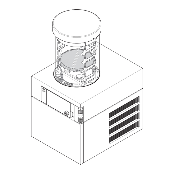
Page 34: Fitting The Manifold Acrylic Drying Chamber
5 | Installation BÜCHI Labortechnik AG Fig. 21: Fitting the acrylic drying chamber 1 Cover 2 O-ring, dia. 300 mm 3 Cylinder 4 Intermediate plate 5 Ice condenser 6 Rack Precondition: R The 300 mm O-ring is fitted in the groove above the ice condenser. Remove all parts of the drying chamber from the packaging and check for dam- age. -
Page 35: Fitting The Stopper Acrylic Drying Chamber
BÜCHI Labortechnik AG Installation | 5 Fig. 22: Fitting the manifold acrylic drying chamber 1 Cover 2 O-ring, dia. 300 mm 3 Cylinder 4 Intermediate plate 5 Ice condenser 6 Rack Precondition: R The 300 mm O-ring is fitted in the groove above the ice condenser. Remove all parts of the drying chamber from the packaging and check for dam- age. -
Page 36: Assembling The Manifold Drying Rack
5 | Installation BÜCHI Labortechnik AG Fig. 23: Fitting the stopper acrylic drying chamber 1 Hand wheel 2 Cover 3 O-ring, dia. 300 mm 4 Cylinder 5 Springs 6 Ice condenser 7 Intermediate plate 8 Rack 9 Hook Precondition: R The 300 mm O-ring is fitted in the groove above the ice condenser. Remove all parts of the drying chamber from the packaging and check for dam- age. -
Page 37: Fitting The Non-Heatable Shelf
BÜCHI Labortechnik AG Installation | 5 The manifold drying rack enables freeze-drying of samples in flasks. The manifold drying rack is a modular, expandable design. Fig. 24: Manifold drying rack 1 Manifold valve 2 Manifold drying rack 3 Base plate 4 Seal, ISO-KF 40 5 Clamp, ISO-KF 40 6 Connection, ISO-KF 40 Precondition:... - Page 38 5 | Installation BÜCHI Labortechnik AG Fig. 25: Non-heatable shelf 1 Non-heatable shelf Sliding the shelves into the rack Fig. 26: Non-heatable shelf in rack 1 Rack 2 Slot for shelf 3 Stop 4 Connections for shelves 5 Non-heatable shelf 6 Lug Precondition: R The rack is mounted on top of the ice condenser.
-
Page 39: Fitting Heatable Shelves
BÜCHI Labortechnik AG Installation | 5 5.5.7 Fitting heatable shelves Shelves can be fitted in the drying chambers. The shelves allow the freeze-drying of samples in vials or as loose samples. The shelves slide into a rack inside the drying chamber. - Page 40 5 | Installation BÜCHI Labortechnik AG Sliding the shelves into the rack Fig. 28: Heatable shelf in rack 1 Rack 2 Slot for shelf 3 Temperature sensor (option) 4 Stop 5 Connections for shelves 6 Electrical connector for heatable shelf 7 Heatable shelf 8 Lug Precondition: R The rack is mounted on top of the ice condenser.
- Page 41 BÜCHI Labortechnik AG Installation | 5 Plugging in the heatable shelf connector Fig. 29: Plugging in heatable shelf 1 Electrical connector for heatable shelf 2 Connections for shelves 3 Ring Precondition: R The shelf is slotted into the rack. Push the electrical connector (1) onto one of the shelf connections (2) while simul- taneously twisting the ring (3) anti-clockwise.
-
Page 42: Assembling Manifold Valves
5 | Installation BÜCHI Labortechnik AG Temperature sensor connector 6 5 4 Fig. 31: Temperature sensor connector 1 Heatable shelf 2 Connection for temperature sensor 3 Marking on temperature sensor con- 4 Marking on temperature sensor con- nection nector 5 Ring 6 Temperature sensor connector 7 Temperature sensor Plugging in the temperature sensor connector:... - Page 43 BÜCHI Labortechnik AG Installation | 5 Remove manifold valve (2) from the packaging. Fit manifold valve (2) onto the connection on the top-mount drying rack (1). Manifold valve settings The lever on a manifold valve can be set to the following positions: Fig. 33: Manifold valve 1 Manifold valve 2 Lever...
- Page 44 5 | Installation BÜCHI Labortechnik AG Precondition: R The manifold valve is closed. Fit the evacuation adaptor (3) onto the lever (2). Fit the vacuum tube (5) onto the evacuation adaptor (3). Fix the vacuum tube with the tube clip (4). Connect a vacuum to the vacuum tube (5).
-
Page 45: Operating The Control Panel
BÜCHI Labortechnik AG Operating the control panel | 6 Operating the control panel This section describes the operation of the instrument using the control panel. CAUTION Risk of injury from glass splinters Sharp objects can damage the display. Keep sharp objects away from the display. Layout of the control panel Fig. 35: Layout of the control panel Description... -
Page 46: Menu Bar
6 | Operating the control panel BÜCHI Labortechnik AG General function buttons Symbol Description Meaning [Back] The display reverts to the previous view. [Cancel] Cancels an operation. [Add to favourites] Adds the selected item to the [Favourites] menu. [Remove from Removes the selected item from the favourites] [Favourites] menu. -
Page 47: Start Menu
BÜCHI Labortechnik AG Operating the control panel | 6 Menu Meaning Submenu/Action symbol [Configuration] menu — Process settings — Settings — Servicing — Service — System information — Notifications [Messages] menu — Logbook 6.3.1 Start menu On the [Start] menu, parameters can be set manually. Changing parameters Select a parameter by turning the navigation control. - Page 48 Option Explanation [Mobile connec- View The control panel shows a password tion password] for entry in the BUCHI Monitor app. [Mobile connec- View The control unit shows a QR code tion QR code] for reading by the BUCHI Monitor app.
- Page 49 BÜCHI Labortechnik AG Operating the control panel | 6 Action Option Explanation [Vacuum test] Perform vacuum test See Chapter 9.3 "Performing a vac- uum test", page 84 Submenu Service The submenu [Service] contains information on the individual freeze-dryer compo- nents. Action Option Explanation [Refrigerant cir- View...
-
Page 50: Status Bar
6 | Operating the control panel BÜCHI Labortechnik AG Action Option Explanation [L-200] View The following information on the L-200 is available: — Serial number — Firmware version — Hours of duty — Status — PCB Temperature — 48V power supply —... - Page 51 The current parameters of the freeze-drying process are being re-established. Symbols on the status bar Symbol Status The instrument is connected to the BUCHI Cloud. The instrument is defrosting. The instrument is starting up. The instrument is in energy-saving mode. Before the freeze-drying process: Load the top-mount drying rack with a frozen sample.
-
Page 52: Carrying Out Freeze-Drying
6 | Operating the control panel BÜCHI Labortechnik AG Carrying out freeze-drying 6.5.1 Preparing the instrument Time approx. 30min quired: NOTE The conditioning phase can be skipped by tapping [Skip] on the function bar. Navigation path ➔ Start Navigate to the [Start] menu via the navigation path. Tap the function [Start conditioning] on the function bar. -
Page 53: Ending Freeze-Drying
BÜCHI Labortechnik AG Operating the control panel | 6 R The freeze-drying process has been started. Navigate to the [Start] menu via the navigation path. Navigate to the desired parameter using the navigation control. Tap the function [Edit] on the function bar. The control panel highlights the selected parameter in white. -
Page 54: Operating Pro Control Panel
7 | Operating Pro control panel BÜCHI Labortechnik AG Operating Pro control panel This section describes the operation of the instrument using the Pro control panel. CAUTION Risk of injury from glass splinters Sharp objects can damage the display. Keep sharp objects away from the display. Layout of Pro control panel Fig. 36: Layout of Pro control panel Description... - Page 55 BÜCHI Labortechnik AG Operating Pro control panel | 7 Symbol Description Meaning [Cancel] Cancels an operation. [Add to favourites] Adds the selected item to the [Favourites] menu. [Remove from Removes the selected item from the favourites] [Favourites] menu. [Confirm] Confirms an entry. [Edit] Allows the selected item to be edited.
-
Page 56: Menu Bar
7 | Operating Pro control panel BÜCHI Labortechnik AG Menu bar The menus are represented by symbols on the menu bar. Navigation through the menus is by the input controls. The following menus are available: Menu Meaning Submenu/Action symbol — Process control parameters Start menu —... -
Page 57: Method Menu
Option Explanation [Mobile connec- View The control panel shows a password tion password] for entry in the BUCHI Monitor app. [Mobile connec- View The control unit shows a QR code tion QR code] for reading by the BUCHI Monitor app. - Page 58 Display illumination level in %: 0 - ness] [Network] Enter value The following parameters can be edited: Device name/MAC address/DHCP/ System IP address/Subnet mask/ Gateway/DNS server/BUCHI Cloud/ Server IP address [Delete app con- Confirmation question Resets external connections to the nection] instrument. Submenu End point determination...
- Page 59 BÜCHI Labortechnik AG Operating Pro control panel | 7 Action Option Explanation [Refrigerant cir- View The following information on the re- cuit] frigerant circuit is available: — Hours of duty — Compressor — Ice condenser inlet temperature — Ice condenser outlet temperature —...
-
Page 60: Messages Menu
7 | Operating Pro control panel BÜCHI Labortechnik AG Action Option Explanation [L-200] View The following information on the L-200 is available: — Serial number — Firmware version — Hours of duty — Status — PCB Temperature — 48V power supply —... - Page 61 The instrument is starting up. The instrument is in the course of a manual freeze-drying process. The instrument is connected to the BUCHI Cloud. Sample protection is active. L-200 / L-200 Pro Operation Manual Lyovapor 61/96...
-
Page 62: Editing A Method
7 | Operating Pro control panel BÜCHI Labortechnik AG Symbol Status Before the freeze-drying process: Load the top-mount drying rack with a frozen sample. After the freeze-drying process: Remove the dried sample from the top-mount drying rack. The vacuum pump is being brought up to operat- ing temperature. -
Page 63: Setting The Gas Type
BÜCHI Labortechnik AG Operating Pro control panel | 7 Tap the setting [Sample collapse temperature]. The control panel shows a dialog box with a numeric input box. Enter the value in the numeric input box. Tap the function [Save] on the function bar. The setting is saved. - Page 64 7 | Operating Pro control panel BÜCHI Labortechnik AG Tap the action [Steps]. The control panel shows the action Steps. The following settings are available for each step: Setting Option Meaning [Step phase] Primary drying/Sec- Sets the type of step phase. ondary drying [Duration] Enter value...
-
Page 65: Setting The Phases Of A Method
BÜCHI Labortechnik AG Operating Pro control panel | 7 7.5.7 Setting the phases of a method NOTE The settings in the Phase view affect all steps of a phase. Navigation path ➔ Method Navigate to the [Method] menu via the navigation path. Tap the name of the method that you wish to edit. - Page 66 7 | Operating Pro control panel BÜCHI Labortechnik AG Phase Setting Option Meaning [Sec- [Pressure None/Sample None: no action is carried out. ondary action] protection/ Sample protection: if the pressure is drying] Message too high, heating of the shelves is paused.
-
Page 67: Deleting A Method
BÜCHI Labortechnik AG Operating Pro control panel | 7 Deleting a method Navigation path ➔ Method Navigate to the [Method] menu via the navigation path. Tap the name of the method that you wish to edit. The control panel highlights the selected method in green. Tap the function [Delete] on the function bar. -
Page 68: Temperature Difference Test
7 | Operating Pro control panel BÜCHI Labortechnik AG Setting Option Explanation [Pressure Entry of value Specifies the difference between difference the two sensor readings below limit] which the end point is reached. [Duration] Entry of value Specifies the length of time for which the pressure difference test is to be carried out. -
Page 69: Performing Freeze-Drying Using A Method [Pro Control Panel]
BÜCHI Labortechnik AG Operating Pro control panel | 7 Setting Option Explanation [Tempera- Yes/No Switches the temperature differ- ture differ- ence test on or off. ence test] [Start time] Enter setting Sets the time from which the temperature difference test is to be performed. -
Page 70: Starting Freeze-Drying
7 | Operating Pro control panel BÜCHI Labortechnik AG Navigate to the [Method] menu via the navigation path. Tap the function [Method] on the function bar. Tap the method that you wish to use. Tap the function [Activate] on the function bar. The status bar shows the method activated. -
Page 71: Ending Freeze-Drying
BÜCHI Labortechnik AG Operating Pro control panel | 7 7.8.4 Ending freeze-drying Navigation path ➔ Start Precondition: R The status bar is showing the status Hold. Navigate to the [Start] menu via the navigation path. Tap the function [Aerate] on the function bar. Answer YES to the confirmation question. -
Page 72: Starting Freeze-Drying
7 | Operating Pro control panel BÜCHI Labortechnik AG Navigation path ➔ Start Navigate to the [Start] menu via the navigation path. Tap the function [Start conditioning] on the function bar. The temperature in the ice condenser decreases to operating temperature. The vacuum pump is brought up to operating temperature. -
Page 73: Ending Freeze-Drying
BÜCHI Labortechnik AG Operating Pro control panel | 7 Tap the function [Save] on the function bar. The setting is saved. The dialog box closes. 7.9.4 Ending freeze-drying Navigation path ➔ Start Precondition: R The sample is dry. Navigate to the [Start] menu via the navigation path. Tap the function [Aerate] on the function bar. -
Page 74: Mobile Connection
Notifications keep the user informed of the status of the instrument. Similar to the display on the control panel, the BUCHI Monitor app shows the current settings and actual readings. Depending on the control unit, the BUCHI Monitor app shows either the alphanumeric data only or the data and progression graph (control panel Pro) process. -
Page 75: Handling Data
The following port has to be enabled in the firewall on the internet gateway: — Port 443 (HTTPS) open for TCP In order to use the BUCHI Cloud a DNS server must be configured on the inter- face unit. NOTE If there is no DNS server available, the BUCHI Cloud connection must be configured by entering the IP address. -
Page 76: Assigning A Dynamic Ip Address
Select the option [Yes]. 5 The IP address will now be dynamically assigned. Enabling the control panel on the BUCHI Cloud To use the BUCHI Monitor app, enable access to the BUCHI Cloud on the control panel. Navigation path ➔ Configuration ➔ Settings ➔ Network➔ BUCHI Cloud Navigate to the action [BUCHI Cloud] via the navigation path. -
Page 77: Layout Of Buchi Monitor App
R The BUCHI Monitor app is installed. Switch on the instrument. 8.9.1 Generating a QR code To connect the BUCHI Monitor app to the instrument, generate a QR code on the in- strument control panel. Navigation path ➔ Configuration ➔ Settings ➔ Mobile connection QR code Navigate to the action [Mobile connection QR code] via the navigation path. -
Page 78: Scanning The Qr Code
R The control panel shows the instrument's QR code. Start the BUCHI Monitor app on the mobile device. Tap the symbol [List]. The display shows a list of instruments that are connected to the BUCHI Monitor app. Tap the [(+)] sign in the top left corner. -
Page 79: Connecting The Instrument And App Using A Password
R The BUCHI Monitor app is installed. Switch on the instrument. 8.10.1 Generating a password To connect the BUCHI Monitor app to the instrument, generate a password on the in- strument control panel. Navigation path ➔ Configuration ➔ Settings ➔ Mobile connection password Navigate to the action [Mobile connection password] via the navigation path. -
Page 80: Removing The Instrument From The App
Removing the instrument from the app Start the BUCHI Monitor app on the mobile device. Tap the symbol [List]. The display shows a list of instruments that are connected to the BUCHI Monitor app. Tap the instrument that you wish to remove. -
Page 81: Remotely Retrieving Process Data
Tap [OK] to save the settings. 5 The display shows the [Settings] screen. 8.13 Remotely retrieving process data The data for the process currently running can be retrieved on the BUCHI Monitor app. Precondition: R The BUCHI Monitor app is connected to the instrument. -
Page 82: Cleaning And Servicing
Users may only carry out the servicing and cleaning operations described in this sec- tion. Any servicing and repair work which involves opening up the casing may only be car- ried out by BUCHI service technicians. Regular maintenance work Component... - Page 83 BÜCHI Labortechnik AG Cleaning and servicing | 9 Component Action Frequency View Wipe down the display with a damp Monthly cloth. L-200 / L-200 Pro Operation Manual Lyovapor 83/96...
-
Page 84: Performing A Leak Test
9 | Cleaning and servicing BÜCHI Labortechnik AG Performing a leak test The leak test checks the vacuum system for possible leaks. Time 45min quired: NOTE The leak test can be aborted by tapping [Stop] on the function bar. Navigation path ➜... - Page 85 BÜCHI Labortechnik AG Cleaning and servicing | 9 Navigation path ➜ Configuration ➜ Servicing ➜ Vacuum test Precondition: R Conditioning of the instrument has been completed. R A top-mount drying rack is fitted. R The top-mount drying rack does not contain a sample. Navigate to the action [Vacuum Test] via the navigation path.
-
Page 86: Help With Faults
10 | Help with faults BÜCHI Labortechnik AG Help with faults 10.1 Troubleshooting Problem Possible cause Action Compressor fails to No power supply to compres- Check the power supply start or switches off and switch on the device. Compressor overheated Allow the compressor to cool down. - Page 87 BÜCHI Labortechnik AG Help with faults | 10 Fault Possible cause Remedy Instrument is not Main valve is incorrectly con- Connect main valve cor- vented nected. rectly (see Chapter 5.3.4 "Assembling the main valve (optional acces- sory)", page 25). L-200 / L-200 Pro Operation Manual Lyovapor 87/96...
-
Page 88: Taking Out Of Service And Disposal
When disposing of equipment observe the local regulations and statutory require- ments regarding waste disposal. 11.2 Returning the instrument Before returning the instrument, contact the BÜCHI Labortechnik AG Service Depart- ment. https://www.buchi.com/contact L-200 / L-200 Pro 88/96 Operation Manual Lyovapor... -
Page 89: Appendix
Appendix 12.1 Spare parts and accessories Use only genuine BUCHI consumables and spare parts in order to ensure correct, safe and reliable operation of the system. NOTE Any modifications of spare parts or assemblies are only allowed with the prior written permission of BUCHI. - Page 90 12 | Appendix BÜCHI Labortechnik AG Description Order no. Image Rack for 6 heatable shelves 11065103 Heatable shelf, aluminum coated, with 11064095 connection cable Sample tray, stainless steel, D 220 mm 11061439 Ferrule, Ø 218 mm 11065816 Drying rack manifold, stainless steel, 11063664 with 12 valves Drip pan, for manifold...
-
Page 91: Accessories
BÜCHI Labortechnik AG Appendix | 12 Description Order no. Image Baseplate, PMMA, for manifold rack 11065733 Suction nipple 11065819 Ampoule adapter for manifold 11065725 with 19 ampoule connections and cap adapter Flask beaker for manifold 100 mL 11066140 with cap adapter and integrated filter Flask beaker for manifold 200 mL 11066141 with cap adapter and integrated filter... -
Page 92: Further Accessories
12 | Appendix BÜCHI Labortechnik AG Description Order no. Image Pressure sensor PPG010 11062228 Pressure sensor Inficon PSG 550 11062229 Pressure sensor Inficon CDG 020 D 11062230 Pressure regulation valve 11064725 Aeration valve 11064724 PT1000 sample temperature sensor 11064031 12.1.3 Further accessories Description Order no. -
Page 93: Spare Parts
BÜCHI Labortechnik AG Appendix | 12 12.1.4 Spare parts Description Order no. Image User interface 11063580 User interface Pro 11063581 O-Ring Ø 300 mm 11065367 Vacuum hose, KF 25, L 1000 mm 11066031 Vacuum clamp KF 16 11064939 Vacuum clamp KF 25 11063662 Vacuum clamp, KF 40 11063663... - Page 94 12 | Appendix BÜCHI Labortechnik AG Description Order no. Image Vacuum sealing KF 25 11063457 Vacuum sealing KF 40 11063659 Vacuum flange adapter, stainless steel, 11064870 KF 16 to KF 25 Blind flange KF 16 11064902 Blind flange KF 25 11063660 Blind flange KF 40 11063661...
- Page 96 T +55 19 3849 1201 F +66 2 862 08 54 F +971 4 313 2861 F +55 19 3849 2907 bacc@buchi.com middleeast@buchi.com latinoamerica@buchi.com www.buchi.com/th-th www.buchi.com www.buchi.com/es-es We are represented by more than 100 distribution partners worldwide. Find your local representative at: www.buchi.com...
Need help?
Do you have a question about the Lyovapor L-200 Pro and is the answer not in the manual?
Questions and answers