Extron electronics PVS 407D Setup Manual
Hide thumbs
Also See for PVS 407D:
- User manual (87 pages) ,
- Installation manual (81 pages) ,
- Setup manual (4 pages)
Table of Contents
Advertisement
Quick Links
PVS 407D • Setup Guide
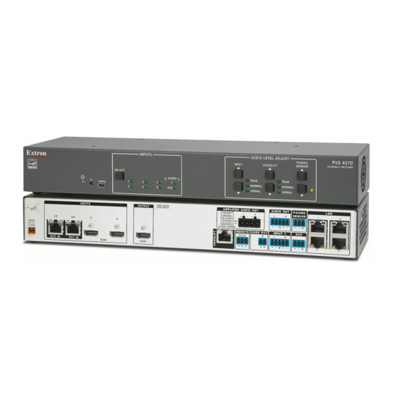
The Extron
PVS 407D is a seven input, one HDMI
®
output switcher with a built-in audio amplifier and
a 4-port Ethernet switch. The PVS 407D is part of
the PoleVault
, PlenumVault
®
Systems, and is used in conjunction with the Extron
PVT digital series of transmitters and Extron speakers. The PVS 407D accepts HDMI and high resolution (RGB) video and audio
signals. The RGB input is digitized at the PVT input wallplate. In addition, the switcher has dedicated ports for connecting the
optional VoiceLift
system and a Page Sensor unit for facility communications.
®
NOTE:
For full installation, configuration, connector wiring, and operation details, see the PVS 407D User Guide, available at
www.extron.com.
Installing and Cabling the PVS 407D Switcher
The PVS 407D may come already pre-mounted within the Extron PMK 560 Projector Mount Kit and the PVM 220 PlenumVault
Mount Kit.
However, if the switcher is not pre-mounted, follow the steps in the system installation guide, supplied with the complete
PoleVault, PlenumVault, or WallVault System. Alternatively, follow the steps in the relevant setup guide for the mounting kit
(PMK 560, PVM 220, WMK 160, or USFM 100). Connect the cables to the switcher as shown in figure 1 and detailed on
ATTENTION:
The PoleVault signal transmission method is specific for PVS 407D switchers working with PVT digital
wallplates. DO NOT connect the input ports to an MTP or XTP system, or to an Ethernet/LAN or data transmission system.
NOTES:
•
The PVS 407D can receive signals from PVT wallplates located up to 150 feet (45 meters) away.
•
RJ-45 termination must comply with the TIA/EIA T 568A or 568B wiring standards for all connectors. The same standard
MUST be used at both ends of all cables (see the PoleVault System Installation Manual for details). The cables supplied
with the Extron PoleVault system are terminated to the TIA 568B standard.
•
The use of shielded cable, such as Extron XTP DTP 24 cable, is strongly recommended.
INPUTS
1/2
3/4
SIG
LINK
SIG
LINK
POWER
12V
3A MAX
PVT IN
PVT IN
M
A
Power Connector
AUDIO IN
AUDIO IN
VGA IN
HDMI IN
e
PVT HD RGB
Supplied PVS
HDMI or RGB video/audio,
Switcher External
Inputs1/2 and 3/4,
Power Supply
1 XTP DTP 24 cable with RJ-45 connectors
(12 VDC, 4 A, or
12 VDC, 4.2 A)
Figure 1.
PVS 407D Switcher Connections
, and WallVault
Digital
®
®
PVS 407D
OUTPUT
5
6
HDMI
HDMI
B
G
HDMI
HDMI
Connector
Connector
HDMI Input
HDMI Output to
Sources,
Display Device
Inputs 5 and 6
NOTES:
• If you use cable that has a drain wire, tie the drain wire
to ground at both ends.
• You must connect a ground wire between the MLC
and PVS.
INPUTS
SELECT
AUDIO
R
1
3
5
7
CONFIG
2
4
6
AUX
Audio Output
Line Out
to Speakers
Output
(Audio)
Speaker
PVS terminal
wire color
(left and right)
Red
Positive (+)
Black
Negative (-)
I
AMPLIFIED AUDIO OUT
L
R
DO NOT
GROUND
OR SHORT
4/8
SPEAKER
Ω
OUTPUTS
CLASS 2 WIRING
REMOTE
OVER PVT
RS-232
IR
Tx Rx
G
S G
E
J
K
VoiceLift
Receiver
S G
IR control
Ground (Gnd)
Receive (Rx)
B
A
Transmit (Tx)
MLC 104 IP Plus
RS-232 input
Product Category
AUDIO LEVEL ADJUST
PAGING
INPUT
VOICELIFT
SENSOR
PEAK
PEAK
NORMAL
NORMAL
SIGNAL
SIGNAL
Paging
4-port 10/100 Ethernet Switch
Sensor
Connect as follows:
Input
1. TCP/IP network
2. MLC controller
+V
3. Optional network device
4. Optional network device
L
H
F
AUDIO OUT
LAN
LAN
PAGING
SENSOR
1
3
L
R
+V
INPUT 7
AUX
L
R
2
4
C
D
Aux
Input
Connect to the
Aux Audio
same power supply
Input 7
used by the PVS Switcher.
Ground
Transmit (Tx)
B
B
A
Receive (Rx)
+12 VDC input
MLC 104 IP Plus right side
A B
panel MLS and Power ports
MLS PWR
RS-232 12V
To PVS terminal
MLC
wire color
White
Tx on RS-232 port
Violet
Rx on RS-232 port
Drain wire
Ground (G)
Black
PVS Power Supply (–)
Red
PVS Power Supply (+)
PVS 407D
POLEVAULT SWITCHER
page
2.
1
Advertisement
Table of Contents

Related Manuals for Extron electronics PVS 407D


Summary of Contents for Extron electronics PVS 407D
- Page 1 Systems, and is used in conjunction with the Extron PVT digital series of transmitters and Extron speakers. The PVS 407D accepts HDMI and high resolution (RGB) video and audio signals. The RGB input is digitized at the PVT input wallplate. In addition, the switcher has dedicated ports for connecting the optional VoiceLift system and a Page Sensor unit for facility communications.
- Page 2 It can be configured via RS-232, front panel USB, or TCP/IP for fixed or variable audio output (default is variable). It can be wired for balanced or unbalanced signals (see the PVS 407D User Guide for method).
- Page 3 NOTE: Use only the supplied 12 V, 4 A or 12 V, 4.2 A power supply for this switcher. The PVS 407D power supply can support a typical system: for example, a PVS 407D, 2 PVT Wallplates, 2 or 4 speakers, an MLC 104 IP Plus with an IRCM DV+, and a VoiceLift Microphone system.
- Page 4 Front Panel Operation and Configuring the PVS 407D Switcher For full details of front panel operation and switcher configuration, refer to the PVS 407D User Guide, and the MLC 104 IP Plus User Guide. For VoiceLift and Page Sensor installation and operation details, refer to the VoiceLift System User Guide and the Priority Page Sensor Kit Installation Instructions.
Need help?
Do you have a question about the PVS 407D and is the answer not in the manual?
Questions and answers