
Related Manuals for Frima VarioCooking Center 112T


Summary of Contents for Frima VarioCooking Center 112T
- Page 1 Original installation instructions IMPORTANT: Please read this manual carefully before using the appliance. 112T - 112L...
- Page 2 - 2 -...
-
Page 3: Table Of Contents
Contents Contents Compliance certificate Fire precautions General safety instructions After-Sales Service, Warranty, Disposal Data plate Description of the appliance Size of the appliance model 112T Size of the appliance model 112L Handling Transport and removal from pallet Space requirements of the appliance Installation Height adjustment Electrical connection... - Page 4 - 4 -...
-
Page 5: Compliance Certificate
FRIMA declara que estos productos son conformes con las siguientes Directivas Europeas: FRIMA kinnitab, et antud tooted vastavad järgmistele EU normidele: FRIMA déclare que ces produits sont en conformité avec les directives de l’Union Européenne suivantes: FRIMA vakuuttaa, että nämä tuotteet täyttävät seuraavien EU direktiivien vaatimukset: FRIMA declares that these products are in conformity with the following EU directives: FRIMA δηλώνει... - Page 6 Explanation of symbols Warning Please read this manual carefully before using the appliance. Incorrect installation, set-up, troubleshooting or maintenance and changes made to the This manual is intended for the installer. appliance may lead to damage, injury or even For operating instructions for the appliance, death.
-
Page 7: Fire Precautions
General safety instructions Information Standards mentioned apply only in France. In all other countries, national standards and regulations apply. Any damages resulting from non-observance of these instructions are not under warranty. Danger! The installation and connection of our appliances must only be carried out by specially trained and authorised qualified professionals and in compliance with regulations. -
Page 8: After-Sales Service, Warranty, Disposal
After-Sales Service, Warranty, Disposal After-Sales Service For the after-sales service, you should firstly contact your installer. These details should be filled in in the user manual at the time of installation. Warranty The obligation of the manufacturer is limited to any separate part deemed to be faulty and for which a quality fault can be claimed. -
Page 9: Data Plate
Data plate Data plate: Description Product name Description of model (112T / 112L) Supply voltage Mains power Water pressure VarioCooking Center serial number © For all telephone enquiries you must pro- vide this number Name of the person who manufactured the appliance Each VarioCooking Center is made by one... -
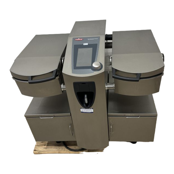
Page 10: Description Of The Appliance
Description of the appliance Description Core temperature probe with 6 measurement 10. Tank emptying lever points 11. Cooking tank Cover 12. Bypass Hook for basket handle 13. Water filling duct Min/Max markings for oil filling and tank 14. Bypass measurement scale 15. - Page 11 Description of the appliance 19. Connection for options: Energy optimisation 23. Technical compartment B: system or Ethernet cable 24. Cover to access water connection and equi- 20. Technical compartment A: potential connection Connection of the appliance 25. Waste water drainage 21.
-
Page 12: Size Of The Appliance Model 112T
Size of the appliance model 112T (1) Waste water drainage DN40 (2) Cold water supply G3/4 (3) Electricity supply (4) Energy optimisation - (Option) (5) Ethernet - (Option) (6) Equipotential connection M6 x 10 (7) Interchangeable foot (20/60 mm) Minimum gap This drawing is not to scale - 12 -... - Page 13 Size of the appliance model 112T with underframe table This drawing is not to scale - 13 -...
-
Page 14: Size Of The Appliance Model 112L
Size of the appliance model 112L (1) Waste water drainage DN40 (2) Cold water supply G3/4 (3) Electricity supply (4) Energy optimisation - (Option) (5) Ethernet - (Option) (6) Equipotential connection M6 x 10 (7) Interchangeable foot (20/60 mm) Minimum gap This drawing is not to scale - 14 -... - Page 15 Size of the appliance model 112L with underframe table This drawing is not to scale - 15 -...
-
Page 16: Handling
Handling Transport and removal from pallet Stacking of packaged appliances Fig. 1 200 Kg Max The appliance may be stacked in its original packa- ging. Do not under any circumstances stack more than 3 appliances, or 200 kilograms on the bottom package. - Page 17 Handling Equipment alone Handling using a forklift truck Warning Fig. 1 To avoid damaging the appliance, it is not recom- mended to handle it without its packaging using a forklift truck, pallet truck or equivalent. Manual handling Fig. 2 Handle the appliance as shown in image Fig 2. To avoid damaging the appliance, make sure the cover is lowered before picking it up or moving it.
-
Page 18: Space Requirements Of The Appliance
Space requirements of the appliance Sizes/gross weight Fig. 1 VCCM 112T P (kg) 1100 mm 600 mm 900 mm 23 2/3 1/4" " 3/8" VCCM 112L P (kg) 1240 mm 600 mm 1030 mm 48 4/5 23 2/3 40 1/2 "... -
Page 19: Installation
Installation Minimum space recommended Minimum space recommended Fig. 1 Right/Left only 50 mm If there is limited space available for installation, this 50 mm 50 mm distance may be reduced to zero. 2" 2" Safety distances Fig. 2 Fire hazard ! Use as a fryer. »... - Page 20 - 20 -...
- Page 21 Installation Opening Opening the control panel Fig. 1 (1). Lift up and remove the rotary control button (2). Remove the screws* (3). Push the control panel back (4). Tip the control panel onto the left or right cover, as you wish. Opening the rear panels Fig.
-
Page 22: Height Adjustment
Height adjustment Mounting on an underframe table Fig. 1 Other supports Before leveling the unit itself make sure that the support (table, shelf, underframe table) is properly levelled. Choice of front leg Fig. 2 Our appliances are delivered in a standard version, assembled with a 20 mm leg. - Page 23 Height adjustment Step 2 Fig. 4 Place the spirit level on one of the tanks (A), on the longest side. Now carry out the transverse adjustment (forwards/backwards) of the appliance. In order to do this, adjust the back leg on the side where you have placed the spirit level.
-
Page 24: Electrical Connection
Electrical connection General points and safety Regulations Mains connection cable: • Connect the appliances in accordance with the • Electrical data: see page 26 installation instructions and the instructions • Connection of appliances, for values and on the data plate (See description in chapter connection points see the following pages 25 “data plate”). - Page 25 Electrical connection Observe the colour coding of the conductors. Incorrect connection may lead to electrical shock or damage the equipment. General instructions: see previous page. The connection terminals are located behind the rear face, in the electrical compartment. See detail in Fig. 1 &...
- Page 26 Electrical connection: Connection values Power Curent con~ Standardised Min. recommended (kW) sumption (A) protection (A) cross-section (mm VCCM 112T 3 AC 200V 3 AC 220V 3 NAC 400V 3 NAC 400V Dynamic 3 NAC 415V 3 NAC 415V Dynamic VCCM 112L 3 AC 200V 3 AC 220V 3 NAC 400V...
-
Page 27: Water Supply
Water supply Recommendations: » We recommend that one shut-off valve should be installed per appliance. » The pipe must be bled before connecting the appliance. Fig 2 Connection Fig. 2 Cold water connection (3/4") Pressure & Flow The water pressure should be between 150 kPa and 600 kPa (1.5 - 6 bar) Nominal flow: 0.5 - 1.5m Temperature... -
Page 28: Waste Water Drainage
Waste water drainage DN40 Burn hazard ! » Be careful not to burn yourself, cooking water may be hot when drai- ned! Warning! • Only use a rigid pipe, resistant to steam tempe- rature. (PP Type) Min. 3% • The temperature of waste water is lower than 100 °C Requirements •... - Page 29 Waste water drainage Appliances placed on underframe tables Fig. 1a/b The underframe table is pre-perforated to allow tech- nical components to pass through it. (Drainage, water supply, electricity supply, options) Drainage towards the front of the appliance Fig. 2 If the appliance is assembled with the 60 mm front leg the drainage can be brought to the front.
-
Page 30: First Use
First use Adjustment of the installation height Fig. 1 If the installation height is different from the factory Altitude d'installation settings (0-299m), adjust it. du VCC • Adjust the height in 300m steps • Validate after adjustment SVP contrôler / configurer l'altitude d'installation Calibration 0 m - 299m... -
Page 31: Installation Options
Installation options Foam support Fig. 1 For use with 20 mm legs only! When assembling your equipment with the 20 mm leg, we recommend that you fill the space under- neath for hygiene reasons. A foam support has been specially designed for our appliance. The purpose of this foam support is to fill this restric- ted space, preventing food waste from getting stuck between the appliance and the surface on which it... - Page 32 Installation options Underframe cabinet Fig. 1/2 Crushing hazard ! » Be careful not to crush fingers whilst handling the appliance » Be careful not to let the appliance tip whilst handling it. This cabinet supports the appliance. It can be delive- red with different options: »...
- Page 33 Installation options Energy optimisation system Fig. 1 For clients who require this, our appliance can be connected to such a system. In this case, the appliance with this option should be ordered. A special supply terminal is then pre-assembled (Fig. 4 and 5).
-
Page 34: Conversion Table Troubleshooting
Conversion table Troubleshooting °dH °f °e mmol/l gr/gal(US) mval/kg 1 °dH 1,79 1,25 17,9 0,1783 1,044 0,357 1 °f 0,56 0,70 10,0 0,584 1 °e 1,43 14,32 0,14 0,84 0,286 1 ppm 0,056 0,07 0,01 0,0584 0,02 1 mmol/l 0,001 0,0007 0,00058 1 gr/gal (US) 0,96... - Page 35 - 35 -...
- Page 36 English Subject to technical improvements and typing errors. If you notice a typing error in this booklet, please inform us. Photocopy this page and write your comments, indicating the exact page. Send it to us by fax. Our contact details can be found on the documents delivered with the appliance.
Need help?
Do you have a question about the VarioCooking Center 112T and is the answer not in the manual?
Questions and answers