Table of Contents
Advertisement
Advertisement
Table of Contents

Related Manuals for CTC Union IPM-E1 Series

Summary of Contents for CTC Union IPM-E1 Series
- Page 1 IPM-E1 E1 over IP Multiplexer...
- Page 3 CTC Union Technologies makes no warranty, representation, or guarantee regarding the suitability of its products for any particular purpose, nor does CTC Union assume any liability arising out of the application or use of any product and specifically disclaims any and all liability, including without limitation any consequential or incidental damages.
- Page 4 IPM-8E1-AD IPM-16E1-AD This document is the current official release manual. Please check CTC Union's website for any updated manual or contact us by E-mail at sales@ctcu.com. Please address any comments for improving this manual or to point out omissions or errors to marketing@ctcu.com. Thank you.
-
Page 5: Table Of Contents
Table of Contents CHAPTER 1. INTRODUCTION ............................ 7 1.1 W ..................................7 ELCOME 1.2 F ............................... 7 UNCTIONAL ESCRIPTION 1.3 F ..................................7 EATURES 1.4 IPM ................................7 UTLOOK 1.5 A ..............................7 PPLICATIONS OF 1.6 T .............................. 8 ECHNICAL PECIFICATIONS 1.7 O .............................. -
Page 7: Chapter 1 Introduction
1.1 Welcome Thank you for choosing CTC Union's IP multiplexer product as your migrating solution to an all IP based network. This user manual will help to explain the settings of this equipment. Due to popular demand, this new generation of multiplexers provides the ability to provision via simple point and click Web interface. -
Page 8: Technical Specifications
Chapter 1 Introduction 1.6 Technical Specifications Construction Physical Dimension Height: 44 mm (1U) Width: 320 mm (1, 2 & 4E1), 290 mm (8 & 16E1) Depth: 125 mm (1, 2 & 4E1), 267 mm (8 & 16E1) Weight: 1.4 Kg (1, 2 & 4E1), 2.4kg (8 & 16E1) 100M Ethernet Interface Compliant with 802.3/802.3u standards 100-BaseT with RJ45 connector... -
Page 9: Chapter 2 Installation
Chapter 2 Installation Chapter 2. Installation 2.1 Description This chapter provides the information needed to install IPMux series. It is important to follow the installation instructions to ensure normal operation of the system and to prevent damages from human negligence. 2.2 Unpacking If there is a possibility for future relocation of the IPMux unit, please keep the packing cartons and protective packaging material. -
Page 10: Getting Started
Chapter 2 Installation Figure 2.6.2 IPMux series mounted in a rack 2.7 Getting Started 1. Place both CO and CPE IPMux devices on a flat work surface. 2. Connect the Ethernet cable to the CO IPMux device's WAN port and the other end of the Ethernet cable to the CPE IPMux device's WAN port. -
Page 11: Chapter 3. Configuration And Operation
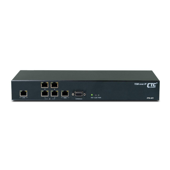
Chapter 3 Configuration and Operation Chapter 3. Configuration and Operation 3.1 Description IPMux series consists of the front panel and the rear panel. The views and description of front and rear panels are shown in Figure 3.2.1 and 3.3.1 for details. 3.2 Front Panel Figure 3.2.1 IPMux 1-Port E1 Front Panel Figure 3.2.2 IPMux 2-Port E1 Front Panel... - Page 12 Chapter 3 Configuration and Operation System Indicators PWR (Power On/Off LED) ALM (failures/errors from any of E1 link) RST Button Use this button to restart the system. LAN Ethernet Connector and Indicators The Ethernet interface is a RJ45 connector with two LED indicators and its pin assignments are shown in Figure 3.2.6. Two LED indicators are described below.
-
Page 13: Rear Panel
Chapter 3 Configuration and Operation 3.3 Rear Panel Figure 3.3.1 IPMux 1, 2, 4E1 Rear Panel Figure 3.3.2 IPMux 8E1 Rear Panel Figure 3.3.3 IPMux 16E1 Rear Panel WAN Ethernet Interface: The Ethernet interface is a RJ45 connector with two LEDs and its pin assignments are shown in Figure 3.2.6. Two LED indicators are described below. -
Page 14: Loopback Modes
Chapter 3 Configuration and Operation 3.4 Loopback Modes The IPMux provides two modes of loopback: "E1 Local Loopback" and "E1 Remote Loopback". (Please refer to Figure 3.4.1). Figure 3.4.1 IPMux E1 Loopback Modes 3.5 IP Configuration The IP address, subnet mask, and default gateway address can be setup through RS232 or Telnet. 3.6 Interface Configuration LAN Ethernet port provides the bandwidth control. -
Page 15: Command Line Interface For Setup
Chapter 3 Configuration and Operation 3.9 Command Line Interface for Setup Serial Terminal Emulation When logging into the terminal, set up the RS-232 port as follows: Bit rate: 115200bps Data bit: 8 Parity: none Stop bit: 1 ... - Page 16 Chapter 3 Configuration and Operation CLI Command Description (enable SNMP trap function and set host 192.168.1.200 to receive the trap message) trapget Get SNMP Trap Mode & Host IP ntpset mode server_ip_addr Set NTP Enable Mode & NTP Server IP mode: 0 for disable NTP function, 1 for enable NTP function Example: ntpset 1 192.168.1.201 (enable NTP function and set NTP server address to192.168.1.201)
- Page 17 Chapter 3 Configuration and Operation CLI Command Description address from the remote device only if the local device can communicate with the remote device via its WAN port. EX: ceschset 1 1 172.16.1.2 Example 2: Enable E1 port #1 and specifically set the destination ip and mac address of the remote device.
-
Page 18: Web Based Management
Chapter 3 Configuration and Operation 3.10 Web Based Management Web management is a convenient configuration method that does not require memorizing complex commands. It allows for quick configuration of TDM parameters by placing them all on one configuration page. The web management of IPMux connects via non-standard port 6868 in an effort to detour hackers from accessing the IPMux. -
Page 19: Ip Address Configuration
Chapter 3 Configuration and Operation 3.10.1 IP Address Configuration Change the NMS management IP address, subnet mask and gateway as well as the WAN IP and subnet mask here. Figure 3.10.3 NMS and WAN IP configuration page 3.10.2 Port General Configuration Configure the local LAN port here to enable or disable traffic. -
Page 20: Tdm Configuration
Chapter 3 Configuration and Operation 3.10.3 TDM Configuration This page is the heart of the TDM configuration for the IPMux. Figure 3.10.5 TDM configuration page E1 Port : Chose the port to be configured from the pull-down Port Status : Enable or Disable the E1 port Remote MAC : Enter the MAC address of the remote E1 port for connection Remote IP Addr : Enter the IP address of the remote WAN. -
Page 21: Alarm History Display
Chapter 3 Configuration and Operation 3.10.4 Alarm History Display Alarm history is a read-only display. The screen supports refreshing, clearing or exporting the alarm log. Figure 3.10.6 Alarm History page 3.10.5 Time Configuration Select each parameter field, key in the correct value, press [Enter]. After finishing all fields, click "Setting". Figure 3.10.7 Time Setting page... -
Page 22: Backup & Restore Configuration
Chapter 3 Configuration and Operation 3.10.6 Backup & Restore Configuration The IPMux provides backup and restore of system configuration via TFTP server. Enter the TFTP server's IP address and the configuration filename (case sensitive), select the appropriate check box and function button. Figure 3.10.8 Backup and Restore page 3.10.7 Save and Reboot Configuration The Csave and Reboot page lets the configuration changes be stored in non-volatile storage and lets the IPMux... -
Page 23: Firmware Upgrade
Chapter 3 Configuration and Operation 3.10.8 Firmware Upgrade Occasionally, updated firmware may become available to add features or fix previously unknown issues. The upgrade method uses TFTP server to transfer new image to the IPMux. The new image is then written to the flash and will be available at next reboot. -
Page 24: Appendix
Appendix A Appendix A) Script for resetting IPMux to default I Script for setting the device back to default I ( LAN bandwidth is 400 kbps) Script for setting CO site configuration back to default I #Execute global chip initialization #Configure an ip address for the WAN port srcnet 172.16.1.1 255.255.255.0 #Configure an ip address and gateway for the NMS port... - Page 25 Appendix A Script for setting CPE site configuration back to default II srcnet 172.16.1.2 255.255.255.0 ipset 192.168.2.11 255.255.255.0 172.16.1.1 cespwidset 1 1 1 pktsize 1 1 jitterbd 1 1 ceschclkset 1 0 ceschset 1 1 172.16.1.1 00:02:AB:10:01:01 lanset 1 7 csave C) Script for resetting IPMux to default III Script for setting the device back to default III...
- Page 26 Appendix A csave D) Script for resetting IPMux to default IV Script for setting the device back to default IV (Enable E1 port #1 to #4 and set LAN bandwidth to 400kbps) Script for setting CO site configuration back to default IV srcnet 172.16.1.1 255.255.255.0 ipset 192.168.1.11 255.255.255.0 172.16.1.2 #Set both transmitting and receiving pseudowire ID to 1 for E1 port#1...
- Page 27 Appendix A jitterbd 2 1 jitterbd 3 1 jitterbd 4 1 ceschclkset 1 0 ceschclkset 2 0 ceschclkset 3 0 ceschclkset 4 0 ceschset 1 1 172.16.1.1 00:02:ab:10:01:01 ceschset 2 1 172.16.1.1 00:02:ab:10:01:01 ceschset 3 1 172.16.1.1 00:02:ab:10:01:01 ceschset 4 1 172.16.1.1 00:02:ab:10:01:01 lanset 1 7 csave E) Script for resetting IPMux to default V...
- Page 28 Appendix A Script for enable order wire at CPE site #Set transmitting and receiving pseudowire ID to 5 for E1 port#5 cespwidset 5 5 5 #Enable E1 port#5, and specifically set the destination IP and MAC #addresses of the remote device (CO). ceschset 5 1 172.16.1.1 00:02:ab:10:01:01 csave Script for disable order wire at both CO and CPE sites...
- Page 29 Revision History Version Date Descriptions 2014/7/3 Change factory defaults title to ~~CO/CPE device settings CO Device (Factory Defaults) Last page image (remove certificate logos)
Need help?
Do you have a question about the IPM-E1 Series and is the answer not in the manual?
Questions and answers