
Subscribe to Our Youtube Channel
Related Manuals for Stanley SPL31A-N


Summary of Contents for Stanley SPL31A-N
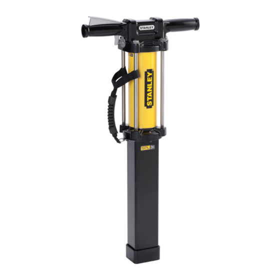
- Page 1 SPL31A SPL31A-N SPL31A-S HYDRAULIC SPIKE PULLER USER MANUAL Safety, Operation and Maintenance © 2013 Stanley Black & Decker, Inc. New Britain, CT 06053 U.S.A. 72926 12/2018 Ver. 12...
- Page 2 NOTES 2 ► SPL31 User Manual...
-
Page 3: Table Of Contents
REPAIRS AND / OR SERVICE TO THIS TOOL MUST ONLY BE DONE BY AN AUTHORIZED AND CERTIFIED DEALER. For the nearest certified dealer, call Stanley Infrastructure at (503) 659-5660 and ask for a Customer Service Representative. SPL31 User Manual ◄ 3... -
Page 4: Safety Symbols
SAFETY SYMBOLS Safety symbols and signal words, as shown below, are used to emphasize all operator, maintenance and repair actions which, if not strictly followed, could result in a life-threatening situation, bodily injury or damage to equipment. This is the safety alert symbol. It is used to alert you to potential personal injury hazards. -
Page 5: Safety Precautions
SAFETY PRECAUTIONS Tool operators and maintenance personnel must always • Never wear loose clothing that can become entangled comply with the safety precautions given in this manual in the working parts of the tool. and on the stickers and tags attached to the tool and •... -
Page 6: Tool Stickers & Tags
USE ONLY PARTS AND REPAIR USE ONLY PARTS AND REPAIR PROCEDURES APPROVED BY PROCEDURES APPROVED BY STANLEY AND DESCRIBED IN THE STANLEY AND DESCRIBED IN THE OPERATION MANUAL. OPERATION MANUAL. TAG TO BE REMOVED ONLY BY TAG TO BE REMOVED ONLY BY TOOL OPERATOR. -
Page 7: Hose Types
This hose is not certifi ed non-conductive and must never be used near electrical conductors. HOSE SAFETY TAGS To help ensure your safety, the following DANGER tags are attached to all hose purchased from STANLEY. DO NOT REMOVE THESE TAGS. -
Page 8: Hose Recommendations
HOSE RECOMMENDATIONS 8 ► SPL31 User Manual... -
Page 9: Htma / Ehtma Requirements
HTMA / EHTMA REQUIREMENTS HTMA / EHTMA REQUIREMENTS TOOL TYPE HTMA TYPE I TYPE II TYPE RR TYPE III HYDRAULIC SYSTEM REQUIREMENTS 4-6 GPM 7-9 GPM 9-10.5 GPM 11-13 GPM Flow range (15-23 LPM) (26-34 LPM) (34-40 LPM) (42-49 LPM) Nominal operating pressure 1500 psi 1500 psi... -
Page 10: Operation
OPERATION CHECK HYDRAULIC POWER position. SOURCE 3. Place the spike puller firmly over the spike to be pulled making sure the end of the chute is in full 1. Using a calibrated flowmeter and pressure gauge, contact with the spike plate. check that the hydraulic power source develops a flow of 5-10.5 GPM/15-40 LPM at 2000 psi/140 bar. -
Page 11: Troubleshooting
• Always replace hoses, couplings and other parts • Check fastener tightness often and before each use with replacement parts recommended by Stanley. daily. • Supply hoses must have a minimum working pressure rating of 2500 psi/175 bar. •... -
Page 12: Specifications
SPECIFICATIONS Pulling Force..........................16,647 lbs / 7550 kg Pressure ............................2500 psi/172 bar Maximum Back Pressure........................250 psi/17 bar Flow Range ..................5-10 GPM / 19-38 LPM HTMA Type I - II, RR Porting ..............................-8 SAE O-Ring Couplers ..................HTMA/EHTMA Flush Face Type Male and Female Connect Size and Type ......................3/8 Male Pipe Adapter Weight (without hose whips &... -
Page 13: Handle Assembly
HANDLE ASSEMBLY SPL31A SPL31A-N SPL31A-S Note: Items 3, 16 and 17 are used on model SPL31A-S and SPL31A-N Only. ITEM PART NO. QTY DESCRIPTION 00026 O-RING* (PART OF SEAL KIT) * DENOTES PART IN SEAL KIT 01604 O-RING* (PART OF SEAL KIT) -
Page 14: Parts Illustration
PARTS ILLUSTRATION SPL31A SEE PAGE 6 FOR DECAL P/N’s SPL31A-N SPL31A-S FOR PARTS TO HANDLE ASSEMBLY SEE PAGE 13 PISTON PISTON ROD 14 ► SPL31 User Manual... -
Page 15: Parts List
PARTS LIST SPL31A / SPL31A-N / SPL31A-S ITEM P/N. QTY. DESCRIPTION ITEM P/N. QTY. DESCRIPTION 00596 CAPSCREW SPL31A ROD ASSEMBLY (IN- 72883 CLUDES ITEM 55) 00138 O-RING* (PART OF SEAL KIT) LOWER CYLINDER HEAD 00664 RETAINING RING 72884 (INCLUDES BEARING & HELI-... - Page 16 Stanley Infrastructure 3810 SE Naef Road Milwaukie, Oregon 97267-5698 USA (503) 659-5660 / Fax (503) 652-1780 www.stanleyinfrastructure.com...
Need help?
Do you have a question about the SPL31A-N and is the answer not in the manual?
Questions and answers