Advertisement
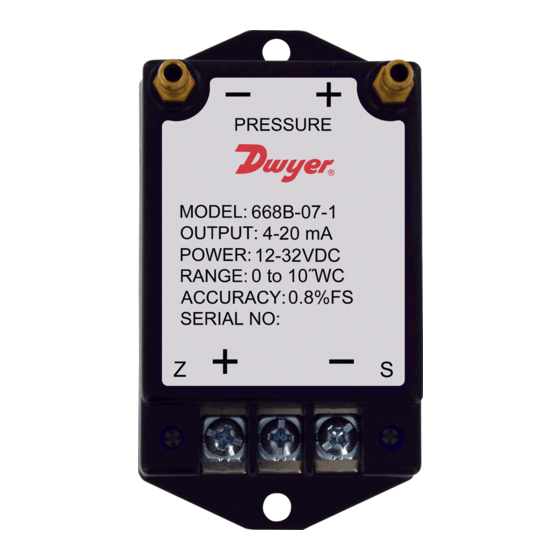
Series 668B/D Compact Differential Pressure Transmitter
Specifications - Installation and Operating Instructions
668B
Our low cost Series 668B/D Compact Differential Pressure Transmitter is capable of
sensing differential gage pressure with ±0.8% FS accuracy, and converts this pressure
difference to a proportional high level analog output for both unidirectional and bi-
directional pressure ranges. Transmitters can withstand up to 15 psig overpressure
with no damage to the unit. The compact, lightweight design makes installation
simple and easy. Units are protected against incorrect wiring, and include a protective
terminal cover.
INSTALLATION
Work on electrical installations must only be carried out by electricians who are
specifically trained for this purpose.
Risk of Shock: Disconnect power supply before making electrical
CAUTION
connections. Contact with components carrying hazardous voltage
can cause electrical shock and equipment may be damaged.
The Series 668B/D is designed to be used with 3/16˝ I.D. push-on tubing. The high
pressure port and the low pressure port are labeled "+" and "-" respectively. For best
results (shortest response times), 3/16˝ I.D. tubing is suggested for tubing lengths up
to 80 feet (25 meters), 1/4˝ I.D. for tubing lengths up to 250 feet (75 meters) and 3/8˝
I.D. for tubing up to 720 feet (220 meters).
The table below shows the maximum wire and receiver resistances as a function of
supply voltage (See Figure 1).
V
V
R
R
RL at Supply Voltage (V
min
max
min
max
12
32
0
1000 RL≤50(Vs-12)
Example: If the Supply Voltage is 24 VDC, RL≤50(24-12)=600 Ω, the load resistance
should not exceed 600 Ω.
DWYER INSTRUMENTS, INC.
P.O. BOX 373 • MICHIGAN CITY, INDIANA 46360, U.S.A.
3-5/32 [80.00]
3-5/32 [80.00]
1-9/32
[32.60]
668D
)
s
3-15/32 [88.00]
2X 3/16
[ø4.80]
1-57/64
1-45/64
[48.20]
[43.25]
668B
3-15/32 [88.00]
2X 3/16
[ø4.80]
668D
SPECIFICATIONS
Service: Air and non-conductive gases.
Accuracy: ±0.8% FS.
Temperature Limits: Operating: 0 to 170°F (-18 to 77°C); Storage: -40 to 185°F
(-40 to 85°C).
Pressure Limits: 15 psig (1.0 bar).
Thermal Effects: ±0.03% FS/°F (±0.054% FS/°C).
Compensated Range: From 40 to 170°F (4.4 to 77°C).
Power Requirements: 12 to 32 VDC.
Output Signals: 4 to 20 mA (2-wire), 0 to 10 VDC (3-wire), or 0 to 5 VDC (3-wire).
Zero Adjustment: Accessible under the small terminal cover.
Electrical Connection: Terminal strip.
Process Connection: 3/16˝ OD barbed brass for 1/8˝ ID push-on tubing.
Enclosure: Stainless steel and PC+ABS alloy, UL 94 V-0 rated.
Weight: 4.0 oz (113 g).
Agency Approvals: CE.
1500
1000
500
0
0
Phone: 219/879-8000
Fax: 219/872-9057
Bulletin P-668BD
1-45/64
[43.25]
1-3/16
[30.20]
1-7/32
[30.80]
3-21/32
[92.94]
OPERATING
REGION
10
20
30
POWER SUPPLY VOLTAGE
*Loop Resistance = Wire Res. + Receiver Res.
Figure 1
www.dwyer-inst.com
e-mail: info@dwyermail.com
1-13/32
[35.60]
1-57/64
[48.20]
40
Advertisement
Table of Contents

Subscribe to Our Youtube Channel
Related Manuals for Dwyer Instruments 668B Series


Summary of Contents for Dwyer Instruments 668B Series
- Page 1 Example: If the Supply Voltage is 24 VDC, RL≤50(24-12)=600 Ω, the load resistance should not exceed 600 Ω. OPERATING REGION POWER SUPPLY VOLTAGE *Loop Resistance = Wire Res. + Receiver Res. Figure 1 DWYER INSTRUMENTS, INC. Phone: 219/879-8000 www.dwyer-inst.com P.O. BOX 373 • MICHIGAN CITY, INDIANA 46360, U.S.A. Fax: 219/872-9057 e-mail: info@dwyermail.com...
- Page 2 Return Goods Authorization number before shipping the product back for repair. Be sure to include a brief description of the problem plus any additional application notes. Figure 4 ©Copyright 2015 Dwyer Instruments, Inc. Printed in U.S.A. 11/15 FR# 444276-00 DWYER INSTRUMENTS, INC.
Need help?
Do you have a question about the 668B Series and is the answer not in the manual?
Questions and answers