Advertisement
Quick Links
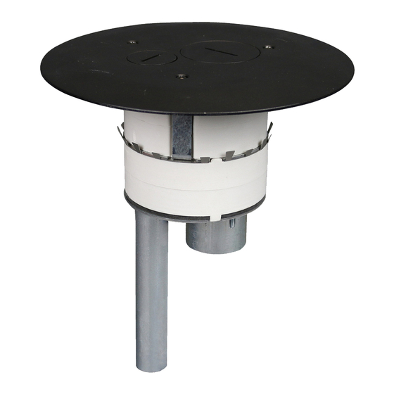
4" Furniture Feed Poke-Thru Device
INSTALLATION INSTRUCTIONS
Installation Instruction No.: 1 004 301 – January 2005
Products Covered: AV3STC, 4FFATC, 4FFCTC
CAUTION DO NOT operate tile stripper or resurfacing equipment over top of covers. This may result in damage to the
surface finish of the product.
Suitable for use in air handling spaces in accordance with Sec. 300-22 (C) of the National Electrical Code.
Step 1 Layout and locate position of hole(s).
CAUTION: Spacing is limited to 2 feet on center and no
more than one hole per each 65 sq. ft. [6 sq. m]
of floor area in each span.
24" [610mm] Min
Center – Center
CAUTION: Be certain to drill hole at least 4" [102mm] from any wall or
pillar to leave enough room for Poke-Thru cover assembly.
Step 3 Core drill hole.
4" [102mm] Diameter Core Drill
4 1/16" [103mm] Actual Diameter
Step 4 Stem Assembly:
Catalog No. AV3STC
Insert stem into hole.
Push Down
CAUTION: Poke-Thru cannot be rotated in
hole after inserted into floor.
Walker
®
electrical systems conform to and should be properly grounded
in compliance with requirements of the current National Electrical Code
or codes administered by local authorities.
All electrical products may present a possible shock or fire hazard if
improperly installed or used. Walker electrical products may bear the
mark as UL Listed and/or Classified and should be installed in
conformance with current local and/or the National Electrical Code.
IMPORTANT: Please read all instructions
before beginning.
Step 2 Remove 7" dia. [178mm] section from carpet
or tile. Use template provided.
CAUTION: For tile installations up to a maximum of
3/4" [19.1mm] thick.
NOTE: For tile thickness greater than 3/4" [19.1mm]
consult factory.
Step 5 Cover Assembly:
7"
[178mm]
Catalog No. 4FFCTC.
Remove disposable plate
and replace with carpet/tile
flange. Install with three (3)
#6-32 x 3/8" [9.5mm] PHMS.
#6-32 x 3/8" PHMS
three (3) required
Advertisement

Related Manuals for LEGRAND AV3STC


Summary of Contents for LEGRAND AV3STC
- Page 1 Installation Instruction No.: 1 004 301 – January 2005 Products Covered: AV3STC, 4FFATC, 4FFCTC CAUTION DO NOT operate tile stripper or resurfacing equipment over top of covers. This may result in damage to the surface finish of the product.
- Page 2 Step 6 Complete assembly: Catalog No. 4FFTATC Step 7 With the assembly installed, remove the screw plugs and install conduit fittings as necessary. Attach conduit to adapter. Push Down 1 1/4" Trade Size Flexible EMT. Not required For Communication Conduit Fitting. 3/4"...
- Page 3 The AV3STC poke-thru stem with the 4FFCTC service head fitting, the 4FFATC factory assembled poke-thru device are for use with 1, 1-1/2, and 2 hr rated unprotected reinforced concrete floors and 1, 1-1/2 or 2 hr rated floors employing unprotected steel floor units and concrete topping (D900-Series Designs), or concrete floors with suspended ceilings.
- Page 4 Carpet Cutout Template Carpet Cutout 7" [178mm] Core Hole 4 1/16" [103mm] CAUTION: When printing copies of this template please be sure template is scaled correctly and is the correct size once it is printed. The Wiremold Company U.S. and International: 60 Woodlawn Street •...
Need help?
Do you have a question about the AV3STC and is the answer not in the manual?
Questions and answers