Advertisement
Quick Links
Download this manual
See also:
User Manual
Advertisement

Related Manuals for Frico AR200


Summary of Contents for Frico AR200
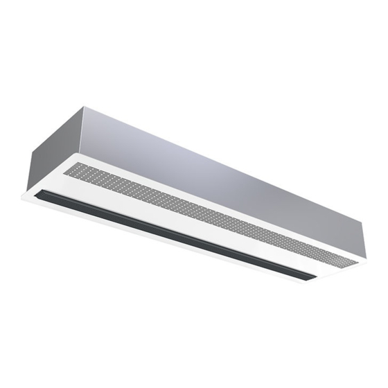
- Page 1 Original instructions AR200 ..22 ..18 ..31 ..36 ..27 ..41 ..46 ..56 ..51...
-
Page 2: Dimensions And Connections
AR200 Dimensions and connections AR210/AR215 1002/1512 940/1450 1042/1552 AR210/215A/E DN15 (1/2”) 92/96 AR220 2003 960 (W), 1000 (A/E) 980 (W), 940 (A/E) 2042 1002 AR220A/E... -
Page 3: Mounting And Installation
AR200 Mounting and installation Fig. 1: The mounting brackets on delivery. Fig. 2: Mounting on threaded bars. 90° Service hatch Fig. 3: Removal of bottom plate Fig. 4: Function of the snap fixing... -
Page 4: Minimum Distance
AR200 Mounting and installation Minimum distance Min 1,8 m Fig. 5 Minimum distance to the floor for AR200E. - Page 5 AR200 Accessories Controls CB30N T10S CB32N RTI2 CB30N AR200A/W, IP44 CB32N AR200E, IP44 IP44 RTI2 IP44 IP30 T10S...
- Page 6 AR200 Accessories Water controls VRS20/25 AV20/25 BPV10 TRVS20/25 SD20 Accessories Type RSK-nr JVF20/25 [SE] VRS20 673 17 99 673 18 00 VRS25 TVVS20 673 92 96 TVVS25 673 92 97 SD20 672 70 37 TVVS20/25 AV20/25 AV20/25 BPV10 BPV10 TVVS20/25...
- Page 7 AR200 Wiring diagrams AR200 A Internal / Ambient regulation option Level 1 AR210A AR220A AR215A °C Blue 230V~ AR210A AR215A AR220A 3µF 4µF 3µF 6µF 10µF 5µF 12µF 14µF 7µF 2 3 4 5 6 CB30N Level 2 AR210A AR220A AR215A °C...
- Page 8 AR200 Wiring diagrams AR200 E Switching box (Brass plates) Group 2 AR210E09 AR220E18 AR215E11 Group 1 400V3~ 230V~...
- Page 9 AR200 Wiring diagrams AR200 E Internal Master-slave NOTE! Remove the internal fuse in the slave unit(s) AR220E AR200E AR220E AR200E AR220E AR200E...
- Page 10 AR200...
- Page 11 AR200...
- Page 12 AR200...
- Page 13 AR200 Wiring diagrams AR200 E Level 1 4 5 6 AR200E 400V3N~ 400V3N~ Only valid for AR220E RTI2 2 3 4 5 6 8 9 10 CB32N Level 2 4 5 6 AR200E 400V3N~ 400V3N~ Only valid for AR220E RTI2...
- Page 14 AR200 Wiring diagrams AR200 W Level 1 AR210W AR220W AR215W °C Blue AR200W AR200W SD20 AR200W TVVS20 230V~ AR210W AR215W AR220W 3µF 4µF 3µF 6µF 10µF 5µF 12µF 14µF 7µF T10S CB30N Level 2 AR210W AR220W AR215W °C Blue AR200W...
- Page 15 AR200 Output charts water AR200 AR200 W Supply water temperature:110 °C Water temperature: 110/80 °C Room temperature: +18 °C Room temperature: +18 °C Outlet air temperature: +35 °C* Type Airflow Output Return water Water Pressure Output * Outlet Water Pressure position temp.
- Page 16 AR200 Output charts water AR200 AR200 W Supply water temperature: 60 °C Water temperature: 60/40 °C Room temperature: +18 °C Room temperature: +18 °C Outlet air temperature: +35 °C* Type Airflow Output Return water Water Pressure Output * Outlet Water...
- Page 17 AR200 Technical specifications | AR200 A without heat 1 Type Output Airflow Sound level*¹ Voltage Amperage Length Weight [kW] [dB(A)] [mm] [kg] AR210A 650/1200 34/50 230V~ 1042 AR215A 950/1750 34/50 230V~ 1552 AR220A 1300/2400 40/54 230V~ 2042 Technical specifications | AR200 E electrically heated 3...
- Page 18 Frico. cubrir instalando varias unidades seguidas. Ámbito de aplicación Asegúrese de que el panel inferior La cortina de aire AR200 ha sido quede accesible y se pueda abrir especialmente diseñada para entornos completamente. con grandes exigencias de diseño. Se La distancia mínima desde la salida de...
- Page 19 Por favor anotar que la valvula de dobles. control debe ser instalada en tubería de agua que da servicio a la cortina . En Frico tenemos las adecuadas para las requeridas en la instalación. Las conexiones (DN15 (1/2”), rosca interior) al serpentín calentador del agua están situadas en la parte superior...
-
Page 20: Mantenimiento
tuberías debe equiparse con una válvula obstrucciones, haciendo innecesario de purga para poder expulsar el aire instalar un filtro independiente. en el momento de poner en servicio la cortina de aire.La válvula de purga Revisión, mantenimiento y reparación del aire y la válvula de drenaje no se Antes de iniciar cualquier tarea de suministran con la batería calentadora. - Page 21 Sobrecalentamiento Cambio de la batería eléctrica (E) Las cortinas de aire con calor eléctrico 1. Marque y desconecte los cables a la están equipadas con una protección batería eléctrica. contra el sobrecalentamiento. Si se 2. Quite los tornillos que sujetan la dispara, aplique el procedimiento batería a la unidad y extráigala.
- Page 22 comprobar lo siguiente: Seguridad • Que la bateriía de agua está sin aire. • Todas las instalaciones con • Que hay suficiente caudal de agua. productos de calor eléctrico deben • Que el agua de entrada tiene la equiparse con un interruptor temperatura de trabajo requerida.
- Page 26 Main offi ce Frico AB Tel: +46 31 336 86 00 Box 102 SE-433 22 Partille mailbox@frico.se Sweden www.frico.se For latest updated information and information about your local contact: www.frico.se...