Table of Contents
Advertisement
Kelly KDZ Series/PM/Sep-Ex Motor Controller User's Manual
Kelly KDZ Series / PM / Sep-Ex
Motor Controller User's Manual
KDZ24200
KDZ24201
KDZ24202
KDZ24203
KDZ24300
KDZ24301
KDZ24302
KDZ24303
KDZ24400
KDZ24401
KDZ24402
KDZ24403
KDZ48200
KDZ48201
KDZ48202
KDZ48203
KDZ48300
KDZ48301
KDZ48302
KDZ48303
KDZ72200
KDZ48400
KDZ72201
KDZ48401
KDZ72202
KDZ48402
KDZ72203
KDZ48403
KDZ72300
KDZ48550
KDZ72301
KDZ48551
KDZ72302
KDZ48552
KDZ72303
KDZ48553
KDZ72400
KDZ48650
KDZ72401
KDZ48651
KDZ72402
KDZ48652
KDZ72403
KDZ48653
KDZ72550
KDZ72551
KDZ64400
KDZ72552
KDZ64401
KDZ72553
KDZ64403
KDZ72650
KDZ72651
KDZ12400
KDZ12401
KDZ12402
KDZ12403
V 3.3
Rev.3.3
Aug. 2013
Advertisement
Table of Contents

Related Manuals for Kelly KDZ Series


Summary of Contents for Kelly KDZ Series
- Page 1 Kelly KDZ Series/PM/Sep-Ex Motor Controller User’s Manual V 3.3 Kelly KDZ Series / PM / Sep-Ex Motor Controller User’s Manual KDZ24200 KDZ48303 KDZ72200 KDZ12400 KDZ24201 KDZ48400 KDZ72201 KDZ12401 KDZ24202 KDZ48401 KDZ72202 KDZ12402 KDZ24203 KDZ48402 KDZ72203 KDZ12403 KDZ24300 KDZ48403 KDZ72300 KDZ24301...
-
Page 2: Table Of Contents
Chapter 3 Wiring and Installation................. 5 3.1 Mounting the Controller..................5 3.2 Connections......................7 3.2.1 Front Panel of KDZ Series or PM Motor Controller:......7 3.2.2 Standard Wiring of KDZ Series or PM Motor Controller....9 3.2.3 Front Panel of KDZ Sep-Ex Motor Controller........13 3.2.4 Standard Wiring of KDZ Sep-Ex Motor Controller...... -
Page 3: Chapter 1 Introduction
This manual introduces the Kelly KDZ Series/PM/Sep-Ex Motor controllers’ features, their installation and their maintenance. Read the manual carefully and thoroughly before using the controller. If you have any questions, please contact the support center of Kelly Controls, LLC. Kelly’s programmable motor controllers provide efficient, smooth and quiet controls for electric vehicles like golf carts, go-carts, electric motorcycles, forklifts and hybrid vehicles, as well as electric boats and industrial motor speed control. -
Page 4: Chapter 2 Main Features And Specifications
(7) Maximum reverse speed is configurable to half of the maximum forward speed. (8) Configurable and programmable with a host computer though RS232 or USB. Provide free GUI which can run on Windows XP/2000, Windows 7 and Vista(recommend using Kelly Standard USB To RS232 Converter). -
Page 5: Specifications
Kelly KDZ Series/PM/Sep-Ex Motor Controller User’s Manual V 3.3 •Low EMC. •LED fault code. •Battery protection: current cutback, warning and shutdown at configurable high and low battery voltage. • Rugged aluminum housing for maximum heat dissipation and harsh environment. •Rugged high current terminals, and rugged aviation connectors for small signal. -
Page 6: Naming Regulations
Kelly KDZ Series/PM/Sep-Ex Motor Controller User’s Manual V 3.3 2.4 Naming Regulations Chapter 3 Wiring and Installation 3.1 Mounting the Controller The controller can be oriented in any position which should be as clean and dry as possible, and if necessary, shielded with a cover to protect it from water and contaminants. - Page 7 Kelly KDZ Series/PM/Sep-Ex Motor Controller User’s Manual V 3.3 Height: 62 millimeters KDZ mounting holes’ dimensions (dimensions in millimeters) Figure 1:...
-
Page 8: Connections
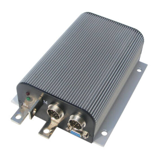
V 3.3 3.2 Connections 3.2.1 Front Panel of KDZ Series or PM Motor Controller: Three metal bars and two plugs (J1, J2) are provided for connecting to the battery, motor and control signals in the front of the controller shown as Figure 2. - Page 9 14- RTN: Signal return Notes: 1. All RTN pins are internally connected. 2. Kelly Ammeter positive connect to 5V power supply of controller, negative to J1-2. 3. Switch to ground is active. Open switch is inactive. Caution: Do not apply power until you are certain the controller wiring is correct and has been •...
-
Page 10: Standard Wiring Of Kdz Series Or Pm Motor Controller
Kelly KDZ Series/PM/Sep-Ex Motor Controller User’s Manual V 3.3 3.2.2 Standard Wiring of KDZ Series or PM Motor Controller Figure 4: KDZ series motor controller standard wiring... - Page 11 Kelly KDZ Series/PM/Sep-Ex Motor Controller User’s Manual V 3.3 Figure 5: KDZ Series motor controller standard wiring without Reversing Contactor...
- Page 12 Kelly KDZ Series/PM/Sep-Ex Motor Controller User’s Manual V 3.3 Figure 6: KDZ PM motor controller standard wiring...
- Page 13 Kelly KDZ Series/PM/Sep-Ex Motor Controller User’s Manual V 3.3 Figure 7: KDZ PM motor controller standard wiring without Reversing Contactor...
-
Page 14: Front Panel Of Kdz Sep-Ex Motor Controller
Kelly KDZ Series/PM/Sep-Ex Motor Controller User’s Manual V 3.3 3.2.3 Front Panel of KDZ Sep-Ex Motor Controller Five metal bars and two plugs (J1, J2) are provided for connecting to the battery, motor and control signals in the front of the controller shown as Figure 8. - Page 15 14- RTN: Signal return Notes: 1. All RTN pins are internally connected. 2. Kelly Ammeter positive connect to 5V power supply of controller, negative to J1-2. 3. Switch to ground is active. Open switch is inactive. Caution: Do not apply power until you are certain the controller wiring is correct and has been •...
-
Page 16: Standard Wiring Of Kdz Sep-Ex Motor Controller
Kelly KDZ Series/PM/Sep-Ex Motor Controller User’s Manual V 3.3 3.2.4 Standard Wiring of KDZ Sep-Ex Motor Controller Figure 10: KDZ Sep-Ex Motor Controller Standard Wiring... -
Page 17: Communication Port
Kelly KDZ Series/PM/Sep-Ex Motor Controller User’s Manual V 3.3 3.2.5 Communication Port A RS232 port of controller is provided to communicate with host computer for calibration and configuration. Figure 11: standard RS232 interface 3.3 Installation Checklist Before operating the vehicle, complete the following checkout procedures. Use LED code as a reference as listed in Table 1. -
Page 18: Chapter 4 Maintenance
Do not connect B+, throttle and so on. The controller may display fault code in some conditions, but it doesn't affect programming or configuration. • Use a straight through RS232 cable or USB Converter provided by Kelly to connect to a host computer. •... -
Page 19: Table 1: Led Codes
Kelly KDZ Series/PM/Sep-Ex Motor Controller User’s Manual V 3.3 Table 1: LED CODES LED Code Explanation Solution No power or Green 1. Check if all wires are correct. switched off 2. Check fuse and power supply. Normal operation Green That’s great! You got solution! ¤... -
Page 20: Contact Us
Kelly KDZ Series/PM/Sep-Ex Motor Controller User’s Manual V 3.3 4.5V. Non-zero throttle ¤¤¤ ¤¤¤¤ Controller won’t allow a direction change unless the on direction throttle or speed is at zero. Fault clears when change throttle is released. Regen ¤¤¤¤ ¤...
Need help?
Do you have a question about the KDZ Series and is the answer not in the manual?
Questions and answers