Table of Contents
Advertisement
Quick Links
*941019-00*
941019-00
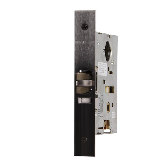
Mortise Lock
1. Prepare door for device and trim (see their
instructions).
2. Prepare door for mortise lock and cylinder (see
preparation on other side of these instructions).
3. Adjust faceplate for door bevel (Figure 2):
(a) Loosen top and bottom faceplate screws.
(b) Pivot faceplate to match door bevel.
(c) Tighten top and bottom faceplate screws.
4. Install mortise lock into door with two #12-12 x 12-24 x 1"
combination screws.
5. Install trim, if required (see trim instructions).
6. If using outside cylinder (Figure 3):
(a) Back out cylinder set screws enough to clear
cylinder mounting hole.
(b) Thread cylinder into mortise lock through
hole in outside face of door.
(c) Tighten the cylinder set screw that is closest
to outside face of door. Remove the other
cylinder set screw.
7. Rotate latch bolt so flat side faces exit direction.
(Figure 4).
8. Install collar, scalp plate, and scalp plate
retaining screws (Figure 1).
7500
Collar
Retaining
screws
Scalp plate
Figure 1
#12-12 x 12-24 x 1"
combination screws
Figure 2
Keyhole
position when
installed
Faceplate
Faceplate screw
Faceplate
}
Equal
angles
Bevel on
edge of
door
Faceplate screw
Installation Instructions
Cylinder set
screws
Door not
shown for
clarity
Figure 3
Flat side of
latch bolt
Exit direction
Top view
Figure 4
Advertisement
Table of Contents

Related Manuals for Von Duprin 7500


Summary of Contents for Von Duprin 7500
- Page 1 *941019-00* 7500 941019-00 Mortise Lock Installation Instructions Collar 1. Prepare door for device and trim (see their instructions). Cylinder set 2. Prepare door for mortise lock and cylinder (see screws preparation on other side of these instructions). Retaining 3. Adjust faceplate for door bevel (Figure 2): screws (a) Loosen top and bottom faceplate screws.
- Page 2 X-X on device template 1” 1-1/4” #12-24 tap lock and strike 4-1/2” min. 2 places clearance required 1-1/4” #12-24 tap 5/8” for 7500 lock 1-5/16” 2 places 3/4” max. 4-11/16” min. diameter 3/8” 5/16” min. clearance required 3/4” max. for SS7500 and 3/8”...
Need help?
Do you have a question about the 7500 and is the answer not in the manual?
Questions and answers