Advertisement
Quick Links
Download this manual
See also:
Service Manual
Advertisement

Related Manuals for Von Duprin 2227


Summary of Contents for Von Duprin 2227
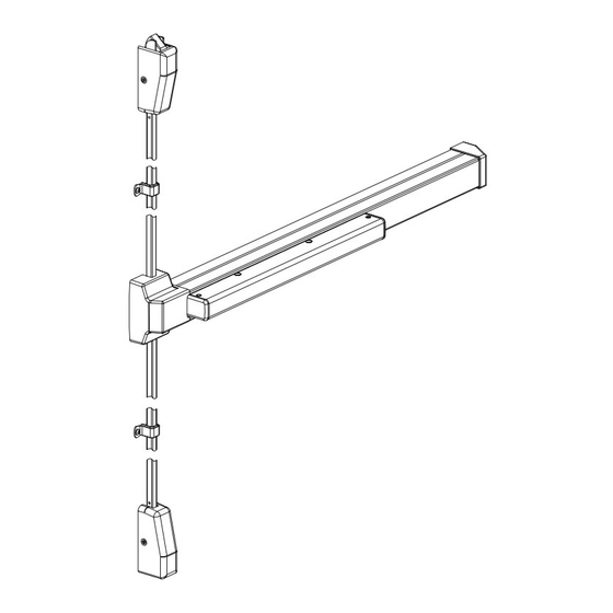
- Page 1 *911334-00* 2227 911334-00 Surface Vertical Rod Device Installation Instructions © Allegion 2014 Customer Service Printed in U.S.A. 911334-00 Rev. 01/14-b 1-877-671-7011 www.allegion.com/us...
-
Page 2: General Information
MAINTENANCE Von Duprin 2227 exit devices are designed and built to be maintenance free; however, such factors as installation, severity of use, environmental conditions, and changes in the condition of the door opening may require that maintenance and/or device adjustment be performed. The following guidelines are recommended to the building owner to insure proper device operation: 1. - Page 3 2227/2227-F PARTS LIST Item Quantity Description In end cap package: #8-18 x 1/2” undercut flat head machine screw In 299/299F strike package: #10-24 x 3/4” flat head machine screw (metal frame) #10-24 x 1-1/2” flat head wood screw (wood frame) In 260U strike package: #10-12 x 10-24 x 1-1/4”...
-
Page 4: Installation
INSTALLATION Cut device if necessary. 1.1. Device length must be at least 3” shorter than opening (Figure 1-1). 1.2. If necessary, cut device so is at least 3” shorter than (Figure 1-2). Measure from middle of gap between doors Double Door Measure from inside of frame... - Page 5 Prepare door. 2.1. Mark center line locations C as shown (Figure 2-1). NOTE 2.2. Tape templates to door aligned with center lines C. For wood fire doors with metal edge, increase backset so device 2.3. Mark and prepare mounting holes per templates. center case clears metal edge.
-
Page 6: Install Device
Install device. 3.1. If using cylinder in trim, install tailpiece guide (packaged with trim) in device. Device cylinder cam Tailpiece guide Bottom of center case Tailpiece Align tailpiece guide to match tailpiece 3.2. Install device to door at center case. #425 sex bolts (shown) or outside trim... - Page 7 Install device (continued). Bracket flush against Device level mechanism case on door Surface Mount Metal Door: #25 drill and #10-24 tap inside Wood Door: 1/8” pilot drill, 1” deep, inside Slide in Mark mounting Sex Bolts mechanism holes and prepare Metal Door: 1/4”...
- Page 8 Install top strike. 299 and 299F Strikes Strike Use shim if necessary for 3/16” spacing Strike 3/16” Latch case Use screws from 299/299F After strike is adjusted, strike package prepare center mounting hole same as other strike #10-24 flat head machine mounting holes and install for metal frame 3/4”...
- Page 9 If door height is less than 84”, cut top rod. (Uncut top rod is about 38-3/4” overall.) 7.1. Find amount to cut off (Figure 7-1). 7.2. Cut top rod (Figure 7-2). 84” Amount to cut off Roll Amount Measure from to cut off bottom of frame 3/8”...
- Page 10 If door height is more than 84”, prepare rod extension. 9.1. Find amount to cut off rod extension (Figure 9-1). IMPORTANT 9.2. Cut rod extension (Figure 9-2). For door heights less than 88”, cut 9.3. Drill hole in rod extension (Figure 9-3). top rod instead of rod extension.
- Page 11 Install and adjust top rod. Install Adjust (screw rod into or out of latch) With door closed: With door open: Latch bolt fully extended Latch bolt flush with and deadlatched or slighly below latch case (will not push in) and release trigger extended Release Latch trigger...
- Page 12 Install rod guides, center case cover, and latch covers. NOTE If using rod or latch guards, skip this step and see rod or latch guard instructions. 12.1. Disconnect top and bottom rods from center case. Slide rod guide bases (with legs of bases against door) onto rods.
- Page 13 TEMPLATE #1 (LHR) 2227/2227-F Device NOTE Refer to Step #2 when For wood fire doors with metal of device using this template edge, increase backset so device center case clears metal edge. Template to scale To edge of LHR door (if edge of 2-3/16”...
- Page 14 TEMPLATE #1 (RHR) 2227/2227-F Device NOTE Refer to Step #2 when For wood fire doors with metal of device using this template edge, increase backset so device center case clears metal edge. Template to scale To edge of RHR door (if edge of 2 3/16”...
- Page 16 Metric Conversion Table inches inches inches inches 1-11/16 3/16 1-3/4 37-1/2 15/16 2-3/16 39-13/16 1011 9/32 2-1/4 1118 5/16 1-1/16 2-9/16 1219 1-1/8 2134 13/32 1-1/4 24-3/4 2235 911334-00 1-1/2 30-3/4 2438 9/16 1-9/16 3048 1-5/8 33-1/2 260U Strike Mounting Holes, 3 Places Metal Frame: #25 drill and #10-24 tap, inside Latch Mounting Holes, 2 Places Wood Frame: 1/8”...
Need help?
Do you have a question about the 2227 and is the answer not in the manual?
Questions and answers