Table of Contents
Advertisement
Quick Links
Download this manual
See also:
User Manual
Advertisement
Table of Contents

Summary of Contents for Shure SCM410E
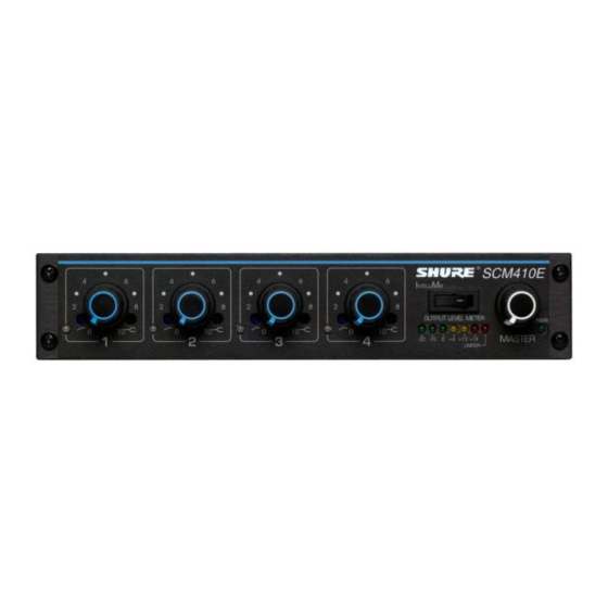
- Page 1 Shure Brothers Incorporated 222 Hartrey Avenue Evanston IL 60202-3696 U.S.A. Model SCM410/SCM410E User Guide SCM410/SCM410E FOUR CHANNEL AUTOMATIC MICROPHONE MIXER 1999, Shure Brothers Incorporated U.S. Patents 4,658,425; 5,297,210 Printed in U.S.A. 27A8690 (SG)
-
Page 2: Table Of Contents
DESCRIPTION ....................FEATURES . -
Page 3: Description
The logic terminals can be used to control external devices. The SCM410 operates on 100–120 Vac power and the SCM410E operates on 220–240 Vac power. Each mixer is supplied with a power cord, rack-mounting hardware, and a link cable. -
Page 4: Rear Panel
1. Power Connector: Unit is energized when the power cord is plugged into a 100–120 Vac (SCM410) or 220–240 Vac (SCM410E) power source. Can be internally modified.Refer to the “Internal Modification” section. NOTE: There is no power On/Off switch on this mixer. -
Page 5: Installation
The SCM410 is supplied with hardware for mounting one or two units to a 19-inch audio equipment rack. The hardware can also be used to rack mount other Shure products, including the SCM268, SCM262, DFR11EQ, and the DP11EQ. Single Mixer (Half Rack) Installation 1. -
Page 6: Table-Top Mounting
TABLE-TOP MOUNTING Adhere the four (4) supplied rubber feet to the bottom of the mixer at each corner, as shown in Figure 9. This will keep it from sliding and protect the table surface. FIXED MOUNTING Top Mount 1. Fasten the straddle brackets to the recessed edges of the chassis, using four (4) bracket screws, as shown in Figure 10. -
Page 7: Scm410 Connections
DIP switch to ON. LINKING MULTIPLE MIXERS If more than four inputs are needed, multiple Shure SCM410, FP410, or SCM810 mixers can be linked by connecting the LINK OUT of the first mixer to the LINK IN of the next mixer, and so on. -
Page 8: Basic Operation
1. Adjust each channel level so that its Overload LED flickers only during very loud speech or noise. 2. Adjust the Low-Cut and High-Frequency controls adjacent to each Input Gain control so that the microphones sound similar. NOTE: The sensitivity of the Intellimix circuitry may allow some channel gating due to static discharge or electrical distur- bance to the power or signal lines. -
Page 9: Specifications
EN55103 (1996); Part 1 (Emissions) and Part 2 (Immunity). +24 dBV Electromagnetic Compatibility (EMC) Statement –18 dBV The SCM410E mixer is intended for use in E1 (residential) and E2 (light industrial) environments, as defined in +14 dBV European EMC standard EN 55103. It meets the applicable tests and performance criteria found in the standard for these environments. - Page 10 Line (Power) Cord, 230–240 Vac (UK) 95B8238 External 50 dB Line Pad 95A8762 Service Statement 95A8778 For additional service or parts information, contact the Shure 95A8889 Service Department at 1-800-516-2525. Outside the U.S.A., contact your authorized Shure Service Center..80C730 .
-
Page 11: Advanced Functions
(Shure’s AMS Update publication contains addition- al applications of advanced logic. This publication is available by contacting the Shure Applications Department.) The follow- ing logic functions are available for each channel: GATE OUT: Follows channel gating and goes to logic “low”... -
Page 12: Suggested Logic Applications
SCM410’s logic capabilities. Note that uses of these functions are not limited to the listed applications. The user is limited only by imagination and creativity. For additional suggestions and solutions to installation problems, contact the Shure Applica- tions Department. Cough Button... - Page 13 Inhibiting Gating for Unwanted Sounds MaxBus attempts to activate only one microphone per sound source. Muting a microphone channel prevents its audio from appearing at the mixer’s output. However, the muted micro- phone still communicates with other mic channels via Max- Bus.
- Page 14 Inhibit Function For information on the inhibit function, refer to the Internal Modifications section. Remote Volume Control The level of the Aux or Master output can be controlled from an external VCA (Voltage Controlled Amplifier) such as the RU- VCA1 from Radio Design Labs (Tel. 1–800–281–2683, or www.rdlnet.com).
-
Page 15: Internal Modifications
2. Locate Voltage Selector switch SW9001 adjacent to power transformer T9000. MODIFYING THE SCM410E FOR 100–120 VAC, 50/60 HZ OPERATION As supplied, the SCM410E uses 220–240 Vac, 50/60 Hz pow- er. To modify it for use with 100–120 Vac, 50/60 Hz power, pro- ceed as follows: 1. - Page 16 LOCAL AUX OPERATION This modification removes the auxilliary audio from the SCM410 outputs. Auxilliary audio originates from the aux in- puts of the Shure SCM810, SCM800, and AMS8100 mixers when linked to the SCM410. MUTE IN PRECEDENCE TO OVERRIDE IN PRECEDENCE Procedure: 1.
- Page 17 When both MUTE IN and OVERRIDE IN logic are grounded, the Override mode will take precedence (as supplied, the MUTE IN takes precedence over OVERRIDE IN). DEAD ZONE ON MUTE IN DEFEAT As supplied, MUTE IN is intended for use as a momentary cough button or privacy function (mute when necessary).
- Page 18 This modification is equivalent to shorting one of the channel OVERRIDE IN to the LOGIC GROUND pin via the high density DB-15 logic connector. With this modification, a channel is al- ways on. SHORTING MUTE IN TO LOGIC GROUND INTERNALLY This modification is equivalent to shorting a channel MUTE IN to the LOGIC GROUND pin via the high density DB-15 logic connector.


Need help?
Do you have a question about the SCM410E and is the answer not in the manual?
Questions and answers