Table of Contents
Advertisement
Quick Links
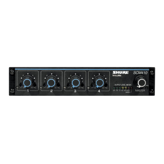
SCM410 SCM410E -- Four-Channel Micro-
phone Mixer
Safety Information
IMPORTANT SAFETY INSTRUCTIONS
1. READ these instructions.
2. KEEP these instructions.
3. HEED all warnings.
4. FOLLOW all instructions.
5. DO NOT use this apparatus near water.
6. CLEAN ONLY with dry cloth.
7. DO NOT block any ventilation openings. Allow sufficient distances for adequate ventilation and install in accor-
dance with the manufacturer's instructions.
8. DO NOT install near any heat sources such as open flames, radiators, heat registers, stoves, or other appara-
tus (including amplifiers) that produce heat. Do not place any open flame sources on the product.
9. DO NOT defeat the safety purpose of the polarized or grounding type plug. A polarized plug has two blades
with one wider than the other. A grounding type plug has two blades and a third grounding prong. The wider
blade or the third prong are provided for your safety. If the provided plug does not fit into your outlet, consult an
electrician for replacement of the obsolete outlet.
10. PROTECT the power cord from being walked on or pinched, particularly at plugs, convenience receptacles,
and the point where they exit from the apparatus.
11. ONLY USE attachments/accessories specified by the manufacturer.
12. USE only with a cart, stand, tripod, bracket, or table specified by the manufacturer, or sold with the apparatus.
When a cart is used, use caution when moving the cart/apparatus combination to avoid injury from tip-over.
13. UNPLUG this apparatus during lightning storms or when unused for long periods of time.
14. REFER all servicing to qualified service personnel. Servicing is required when the apparatus has been dam-
aged in any way, such as power supply cord or plug is damaged, liquid has been spilled or objects have fallen
into the apparatus, the apparatus has been exposed to rain or moisture, does not operate normally, or has
been dropped.
15. DO NOT expose the apparatus to dripping and splashing. DO NOT put objects filled with liquids, such as vas-
es, on the apparatus.
16. The MAINS plug or an appliance coupler shall remain readily operable.
1/25
Advertisement
Table of Contents

Related Manuals for Shure SCM410


Summary of Contents for Shure SCM410
- Page 1 SCM410 SCM410E -- Four-Channel Micro- phone Mixer Safety Information IMPORTANT SAFETY INSTRUCTIONS 1. READ these instructions. 2. KEEP these instructions. 3. HEED all warnings. 4. FOLLOW all instructions. 5. DO NOT use this apparatus near water. 6. CLEAN ONLY with dry cloth.
- Page 2 Shure Incorporated 17. The airborne noise of the Apparatus does not exceed 70dB (A). 18. Apparatus with CLASS I construction shall be connected to a MAINS socket outlet with a protective earthing connection. 19. To reduce the risk of fire or electric shock, do not expose this apparatus to rain or moisture.
-
Page 3: General Description
Any low-impedance dynamic or condenser microphone (including wireless) can be used with the SCM410. Multiple SCM410 mixers can be linked to other SCM410 mixers, as well as to Shure Models FP410, SCM810, and SCM800. Each input channel has a two-band equalizer and three logic terminals. -
Page 4: Operating Principles
• Peak-responding output level meter Operating Principles The operating concept behind the SCM410 Automatic Mixer is Shure's proprietary IntelliMix® circuitry. Intellimix delivers seamless automatic mixing by combining three separate functions: • Noise Adaptive Threshold. Distinguishes between constant background noise (such as air conditioning) and changing sound (such as speech) for each input channel. -
Page 5: Power Led
Note: Country dependant Rear Panel Power Connector Unit is energized when the power cord is plugged into a 100-120 Vac (SCM410) or 220-240 Vac (SCM410E) pow- er source. NOTE: There is no power On/Off switch on this mixer. DIP Switch The 4-position DIP switch provides additional functions. -
Page 6: Dip Switch Functions
12V Phantom Power When this switch is in the ON position, the SCM410 provides 12Vdc phantom power to each XLR microphone in- put. This function is particularly useful when using condenser microphones, since most condenser microphones require phantom power. - Page 7 Shure Incorporated Single Mixer (Half Rack) Installation 1. Attach the short and long rack-mount brackets to the SCM410/E with eight (8) of the supplied bracket screws. INSTALLING HALF RACK MOUNTING BRACKETS 2. Place the mixer in an equipment rack and secure it with the supplied rack-mount screws and plastic washers.
-
Page 8: Fixed Mounting
Shure Incorporated RACK MOUNTING DUAL SCM410/E MIXERS Table-Top Mounting Adhere the four (4) supplied rubber feet to the bottom of the mixer at each corner. This will keep it from sliding and protect the table surface. ATTACHING RUBBER FEET FOR TABLE-TOP MOUNTING... -
Page 9: Scm410 Connections
2. If any condenser microphones are connected, set the +12V phantom power DIP switch to ON. 3. Connect the SCM410 Mic/Line Level Output to the input of mixers, EQs, amplifiers, or recorders. 4. Connect the power cord to 100-120 Vac (SCM410) or 220-240 Vac (SCM410E) -
Page 10: Linking Multiple Mixers
Linking Multiple Mixers If more than four inputs are needed, multiple Shure SCM410, FP410, or SCM810 mixers can be linked by connect- ing the LINK OUT of the first mixer to the LINK IN of the next mixer, and so on. See Figure 2. Leave the LINK IN jack of the first mixer and the LINK OUT jack of the last mixer unconnected. -
Page 11: Basic Mixer Operation
Low-cut filters are used to reduce unwanted low frequency sounds such as footsteps, motorized traffic, and to con- trol proximity effect. The SCM410 has a one-pole, low-cut (high-pass) filter of 6 dB per octave. The low-cut filter al- lows all frequencies above its cutoff point to pass through unchanged. Frequencies below the cutoff are attenuated (see Figure 2). -
Page 12: Specifications
FIGURE 3: HIGH-FREQUENCY SHELVING EFFECTS Specifications Measurement Conditions (unless otherwise specified): Line voltage 120 Vac, 60 Hz (SCM410) or 230 Vac, 50 Hz (SCM410E); full gain; 1 kHz, one channel activated; source impedances: Mic 150Ω ; terminations: Line/Mic Aux 10 kΩ... - Page 13 Shure Incorporated Frequency Response (at 1 kHz , channel controls centered) 50 Hz to 20 kHz ± 2 dB ; −3 dB Corner at 25 kHz Total Harmonic Distortion <0.1% at +4 dBu out , 50 Hz to 20 kHz (through 22 Hz to 20 kHz filter; Input at 12 o'clock and Master at 12 o'clock, all other controls full counterclockwise) Equivalent Input Noise: (150 Ωsource;...
- Page 14 1.75 kg (3.86 lbs) Certifications SCM410: UL LISTED to UL 60065 and cUL LISTED to CAN/CSAC22.2 No. 60065-3 Canada. SCM410E: Conforms to applicable European Union Directives. Low Voltage Directive, 2006/95/EC: Certified to EN 60065. Eligible to bear CE marking. Conforms to European EMC Directive 2004/108/EC. Meets Harmonized Stan- dards EN55103-1:1996 and EN55103-2:1996 for residential (E1) and light industrial (E2) environments.
-
Page 15: Replacement Parts
Shure Incorporated • Conforms to European Regulation (EC) No. 1275/2008, as amended. The CE Declaration of Conformity can be obtained from Shure Incorporated or any of its European representa- tives. For contact information please visit www.shure.com The CE Declaration of Conformity can be obtained from: www.shure.com/europe/compliance... -
Page 16: Optional Accessories
WARNING: Battery packs shall not be exposed to excessive heat such as sunshine, fire, or the like. Logic Connection Specifications The SCM410 logic functions expand the range of installation and control options. Logic can be used for everything from simple cough switches to elaborate computer-controlled room systems. (Shure's AMS Update publication contains additional applications of advanced logic. - Page 17 Shure Incorporated Logic ground is distinct from audio ground. Make all logic ground connections to this pin, including power supply ground of external logic circuitry. To avoid switching clicks, do not connect logic ground to audio, chassis or rack grounds. Logic controls are accessed through the high density DB-15 multi-pin connector on the rear panel (Figure 5).
- Page 18 Shure Incorporated Pin No. Logic Function MUTE IN 4 MUTE IN 1 MUTE IN 2 MUTE IN 3 OVERRIDE IN 4 NO CONNECTION Logic Function Pin No. GATE OUT 1 GATE OUT 2 GATE OUT 3 GATE OUT 4 OVERRIDE IN 1...
-
Page 19: Suggested Logic Applications
Suggested Logic Applications This section contains suggestions on the uses of the SCM410's logic capabilities. Note that uses of these func- tions are not limited to the listed applications. The user is limited only by imagination and creativity. For additional suggestions and solutions to installation problems, contact the Shure Applications Department. - Page 20 Shure Incorporated FIGURE 7: CHAIRPERSON-CONTROLLED MUTING Remote Channel-On Indicators Remote indicators can be used to indicate when a talker's microphone is on. Connect the LEDs and a 5-volt sup- ply to the GATE OUT pins (See Figure 8). To avoid switching clicks in the audio output, do not ground the power supply negative terminal in the audio system or rack ground.
- Page 21 • A paging system loudspeaker • An audio teleconferencing return signal loudspeaker The SCM410 can prevent these and similar sounds from activating microphones as follows: 1. Place one microphone near the unwanted sound source. Connect that microphone's signal to a channel input, - or- connect the unwanted sound source directly into a channel input.
- Page 22 Note: A diode across each relay coil is required to suppress inductive voltage spikes which may damage the SCM410. An existing sound system using 24-volt relays can be used with the SCM410 without modification if the relay coil current draw is under 500 mA.
-
Page 23: Inhibit Function
1. Connect the SCM410 Line output to the VCA line input. 2. Connect the VCA line output to the external device. 3. For remote Master level control, set the SCM410 Master control to 5. Diode Isolation of Logic Controls Two or more control functions that use the same logic pins can be isolated with diodes, as shown in Figure 13. - Page 24 FIGURE 13: DIODE ISOLATION OF LOGIC CONTROLS External Logic Devices SCM410 logic levels are directly compatible with TTL and 5V CMOS logic families. Mixer logic may be used with 15V CMOS logic if a pull-up resistor is used with each GATE output. See Figure 14.
- Page 25 Shure Incorporated Digital Controls or Microcomputers The SCM410 logic pins can interface with custom-designed digital control circuitry or microcomputers for unlimited possibilities of system control functions. 25/25...
Need help?
Do you have a question about the SCM410 and is the answer not in the manual?
Questions and answers