Table of Contents
Advertisement
Quick Links
iConverter XG+
Standalone Module User Manual
Product Overview
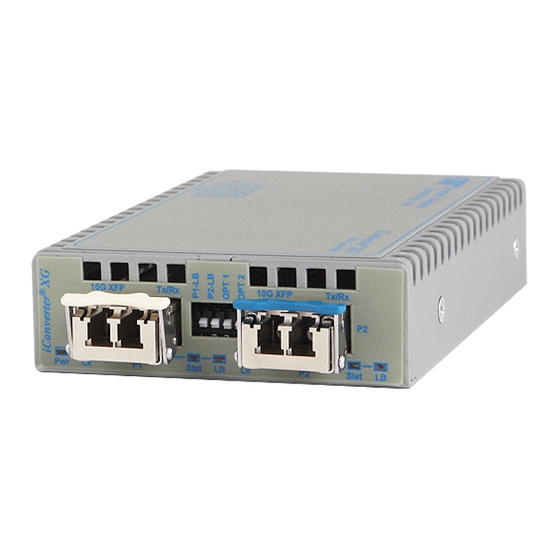
The iConverter XG+ (8599R-xx-x) is a protocol-transparent fiber media converter with two
pluggable transceiver ports supporting data rates from 6G to 11.32G. The iConverter XG+
can be used as a fiber mode converter, a WDM transponder or a fiber repeater supporting
the three Rs (regeneration, retiming and reshaping). The XG+ auto-detects the speed of
the installed transceiver.
The iConverter XG+ supports tunable DWDM and high-power (power level 4) XFP transceivers
up to a combined power of 11.0 watts. Power level 4 XFP transceivers typically perform OTN
functions, where error correction is required to achieve distance requirements. Typically,
most single-mode applications will require power level 2 or power level 3 XFP transceivers.
The iConverter XG+ supports any combination of SFP+ or XFP Power Level transceivers.
Refer to the data sheet for more information on the power level requirements.
Installation Procedure
1) Configure DIP-switches
1) CONFIGURE DIP-SWITCHES
The location of the DIP-switches is shown in Figure 1.
DIP-SWITCH BANK 1
The function of DIP-switch Bank is outlined in Figure 2.
DOWN
Switch
(Default)
SW1
Normal
SW2
Normal
SW3, SW4
Reserved
Figure 2: DIP-switch BANK 1 Definitions
Page 1
UP
P1 Loopback Enabled
P2 Loopback Enabled
Reserved
The XG+ supports port loopback. The SFP+/SFP+ XG+ supports loopback on each individual
port or simultaneous loopback on Port 1 and Port 2. The SFP+/XFP and the XFP/XFP XG+
supports loopback on each individual port, and does not support simultaneous loopback.
In all cases, both transceivers must be installed in the XG+ for the loopback feature to operate.
SW1 - P1 LOOPBACK "P1-LB"
When this DIP-switch is in the DOWN position (factory default), Port 1 (P1) loopback is
disabled. When this DIP-switch is in the UP "P1-LP" position, loopback is enabled on P1.
When enabled, all data received on P1 is transmitted out P1 and all data received on Port 2
(P2) is dropped. No data is transmitted on P2 when loopback is enabled on P1.
NOTE: For XFP models, the loopback feature is dependent on the capability of the
installed XFP. XFPs with XFI-side Loopback feature are required.
SW2 - P2 LOOPBACK "P2-LB"
When this DIP-switch is in the DOWN position (factory default), P2 loopback is disabled. When
this DIP-switch is in the UP "P2-LP" position, loopback is enabled on P2. When enabled, all
data received on P2 is transmitted out P2 and all data received on P1 is dropped. No data
is transmitted on P1 when loopback is enabled on P2.
NOTE: For XFP models, the loopback feature is dependent on the capability of the
installed XFP. XFPs with XFI-side Loopback feature are required.
SW3, SW4 - Reserved
These switches are reserved and must be in the LEFT/DOWN default position.
DIP-SWITCH BANK 2
SW1,SW2, SW3 and SW4 - LINK MODES and CIRCUIT TEST
LINK MODES
These four DIP-switches configure the different link modes available on the XG+. It is
recommended to have link modes set to Link Segment (default setting - all DOWN) during
the initial installation. After the circuit has been tested and operational, configure the module
for the desired mode. Refer to Figure 3 for configuration options.
SW1
SW2
SW3
DOWN
DOWN
DOWN
UP
DOWN
DOWN
DOWN
UP
DOWN
UP
UP
DOWN
DOWN
DOWN
UP
UP
DOWN
UP
DOWN
UP
UP
UP
UP
UP
DOWN
DOWN
DOWN
UP
UP
UP
Figure 3: DIP-switch BANK 2 Link Mode and Self Diagnostic Circuit Test Configurations
* Symmetrical Fault Detect requires bookend configuration of two iConverter XG+s connected
via Port 1. For detailed information on the operation of the different Link Modes, download
the application note "iConverter Link Modes" available on Omnitron's web page:
http://www.omnitron-systems.com/downloads_iconverter.php
SW4
Function
DOWN
Link Segment (default)
DOWN
Asymmetrical Link Propagate P1 to P2
DOWN
Asymmetrical Link Propagate P2 to P1
DOWN
Dual Asymmetrical Link Propagate
DOWN
Remote Fault Detect for P1 and P2
DOWN
RFD + Asymmetrical LP P1 to P2
DOWN
RFD + Asymmetrical LP P2 to P1
DOWN
RFD + Dual Asymmetrical LP
UP
Symmetrical Fault Detect (SFD)*
UP
Self Diagnostic Circuit Test
Page 2
Advertisement
Table of Contents

Related Manuals for Omnitron Systems Technology 8599R Series


Summary of Contents for Omnitron Systems Technology 8599R Series
- Page 1 The XG+ supports port loopback. The SFP+/SFP+ XG+ supports loopback on each individual port or simultaneous loopback on Port 1 and Port 2. The SFP+/XFP and the XFP/XFP XG+ supports loopback on each individual port, and does not support simultaneous loopback. In all cases, both transceivers must be installed in the XG+ for the loopback feature to operate.
- Page 2 TRANSCEIVER INSTALLED IN THE OTHER PORT, THE TRANSMITTER OF THE INSTALLED TRANSCEIVER IS DISABLED. © 2018, Omnitron Systems Technology, Inc. 040-8599R-001B 6/18 Omnitron Systems Technology * 38 Tesla * Irvine, CA 92618 Page 3 949.250.6510 tel * 949.250.6514 fax * www.omnitron-systems.com...
Need help?
Do you have a question about the 8599R Series and is the answer not in the manual?
Questions and answers