Table of Contents
Advertisement
Quick Links
miConverter
10/100 Plus
™
Media Converter
User Manual
Fiber
Tx
Connector Types
Type
Lambda
Lambda
and
Distance
ST
SC
(nm)
(nm)
MM/DF/5km
1120-0-x
1122-0-x
1310
1310
SM/DF/30km
1121-1-x
1123-1-x
1310
1310
SM/DF/60km
1121-2-x
1123-2-x
1310
1310
SM/DF/120km
-
1123-3-x
1550
1550
MM/SF/5km
-
1130-0-x
1310
1550
MM/SF/5km
-
1131-0-x
1550
1310
SM/SF/20km
-
1130-1-x
1310
1550
SM/SF/20km
-
1131-1-x
1550
1310
SM/SF/40km
-
1130-2-x
1310
1550
SM/SF/40km
-
1131-2-x
1550
1310
SM/SF/60km
-
1130-3-x
1310
1550
SM/SF/60km
-
1131-3-x
1550
1310
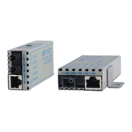
DESCRIPTION
The miConverter
™
10/100 Plus is a 10/100BASE-T
copper to 100BASE-FX fiber media converter. The UTP
copper port can automatically detect the speed, duplex
Page 1
DIP-SWITCH SETTINGS
Link Mode
UTP Mode
LS (default)
AN Auto (default)
LP
MAN 10Mbps HD
MAN 100Mbps HD
MAN 100Mbps FD
Figure 1: DIP-switch Configurations
UTP Mode Selection
The UTP port is configured using the DIP-switches as
shown in Figure 1. There are four modes of operation
based on the position of the DIP-switches. The factory
default configuration is "AN" Auto-negotiation. In the
"AN" mode, the port will advertise 100Mbps Full-Duplex,
100Mbps Half-Duplex, 10Mbps Full-Duplex and 10Mbps
Half-Duplex.
The UTP port can be configured for Manual negotiation
by setting the appropriate DIP-switches. The port can
be configured for 100Mbps Full-Duplex, 100Mbps Half-
Duplex and 10Mbps Half-Duplex.
Link Mode Selection
The miConverter 10/100 Plus can be configured for
several miConverter Link Modes. The DIP-switch
illustration in Figure 1 indicates how to configure the
different Link Modes.
Page 5
mode and crossover mode of the connected device, or it
can be manually configured via DIP-switches.
The 100BASE-FX fiber port operates in Full-Duplex
mode and supports single-mode or multimode fiber with
ST or SC fiber connectors. Single-mode models feature
Bi-Directional fiber and support distances of up to 40km.
The various fiber models options are described in the
table on the first page.
Rx
Several Link Modes (fault-detection capabilities) are
available with the 10/100 Plus, including Link Segment
(Normal Mode), Link Propagate (Link Loss Carry
Forward), Remote Fault Detection and Symmetrical
Fault Detection. The link mode assist in the identification
and isolation of link failures.
POWERING OPTIONS
-1
Barrel Connector and US Power Adapter,100 - 120VAC, 60Hz
Barrel Connector and Universal Power Adapter,
-2
100-240VAC, 50-60Hz (requires AC power cord)
Barrel Connector and European Power Adapter,
-3
100-240VAC, 50-60Hz
Barrel Connector and UK Power Adapter,
-4
100-240VAC, 50-60Hz
Barrel Connector and Australian Power Adapter,
-5
100-240VAC, 50-60Hz
-6
USB Power Adapter Cable
Barrel Connector and US/Japan Power Adapter,
-8
100-240VAC, 50-60Hz
Page 2
Link Segment (LS)
"LS" (factory default) generates and detects a link signal
at each point in the network. Utilizing this configuration,
a loss of a receive link signal will only affect the port
detecting the loss of signal. All the other ports will
continue to generate a link signal. Figure 2(A) indicates
the normal operation of the system without faults. Figure
2(B) indicates a loss of a receive link on the fiber optic
port, the UTP port continues to maintain its link.
Normal Operation
Fiber
UTP
(A)
UTP
Fiber
Switch 1
Converter A
Converter B Switch 2
LS
(B)
Switch 1
Converter A
Converter B Switch 2
LP
(C)
Switch 1
Converter A
Converter B Switch 2
Figure 2a, 2b and 2c: Link Modes
Page 6
WARNING!
Before inserting the Power Adapter, verify
that the power on the unit is appropriate
for your AC line voltage source.
POWER MODES
AC power adapter is available in US, Universal and
Country/Region specific models. Country/Region
specific models feature optional interchangeable
connectors, allowing for compatibility with electrical
outlet types found around the world.
This product should only be used with Omnitron
Supplied Power Unit.
To power the module using the USB cable, connect the
USB Standard Type A connector to a USB port on the
computer. Then connect the connector at the other end
of the cable (barrel connector) to the connector on the
back of the miConverter. Confirm that the module has
powered up properly by checking the power status LED
located on the top of the module.
To power the module using the AC/DC adapter, connect
the AC/DC adapter to the AC outlet. Then connect the
barrel connector at the end of the cable to the back of
the miConverter. Confirm that the module has powered
up properly by checking the power status LED located
on the top of the module.
Link Propagate (LP)
"LP" generates (transmits) a link signal only when a link
signal is detected. Utilizing this configuration, a loss of
a receive link signal will continue to 'propagate' through
to the next port in the network. In Figure 2(C), a loss
of a receive link on the fiber optic port causes the UTP
port to drop its link due to the propagated fiber optic link
state. This setting allows the loss of a link to be detected
by SNMP or other managed network devices to which
the miConverter 10/100 Plus is connected.
NOTE: Only the first loss of a receive link detected by
the miConverter 10/100 Plus turns off the other port's
UTP
transmit link. An additional loss of a receive link on
UTP
the other port has no affect on the miConverter 10/100
Plus. The miConverter 10/100 Plus returns to normal
operation when the first loss of a receive link is restored.
LS
Remote Fault Detect + Link Segment (RFD + LS)
"RFD+LS" generates a link signal only when a link signal
is detected. However, instead of propagating the fault
forward, the loss of link is looped back. In Figure 2(D),
a loss of a received link state is looped back causing the
port to stop transmitted the link state. Because the other
LP
unit is configured for Link Propagate, the UTP port will
drop its link due to the propagated fiber optic link state.
NOTE: It is not permitted to set both Converter A and B
to RFD at the same time; a deadly embrace will occur.
INSTALLATION PROCEDURE
The miConverter 10/100 can be quick-mounted using
the included Velcro
using the optional wall-mounting kit (P/N 4381).
Configure the miConverter 10/100 Plus with the
appropriate DIP-switch settings. The factory default
configuration for the UTP copper port is "AN" Auto-
negotiation and the Link Mode is "LS" Link Segment.
Attach the RJ-45 port of the miConverter 10/100 to
a 10BASE-T or 100BASE-TX PoE capable Ethernet
device, via a category 5 or better cable.
Attach the fiber port of the miConverter 10/100 to a
100BASE-X Fast Ethernet device, via a fiber cable of
appropriate mode and type.
When connecting the dual-fiber models, the miConverter
transmitter (Tx) must attach to the receiver side of its link
partner; the receiver (Rx) must attach to the transmitter.
When using single-fiber (SF) media converter models,
the Tx wavelength on one end has to match the Rx
wavelength on the other. Based on this guideline, the
SF media converter models must be used in pairs, such
as the 1130-1 matched with the 1131-1.
Page 3
Symmetrical Fault Detect (SFD)
"SFD" generates a Link Loss signal on all ports on both
media converters when a loss of link signal is detected
by one of the ports. In Figure 2(E), the pattern of LEDs
gives an indication of the failure point.
NOTE: Both media converters must be configured with
the SFD Link Mode. The SFD function is only supported
by Omnitron Systems equipment.
(D)
Switch 1
(E)
Switch 1
Page 7
strips, or permanently mounted
®
Page 4
LP
RFD+LS
RFD
Converter A
Converter B Switch 2
SFD
SFD
RFD
Converter A
Converter B Switch 2
LED ON
LED
LED OFF
LED Flashing
LED ON or OFF
- LED status depends on the link
type; AN - OFF, MAN - ON
Figure 2d and 2e: Link Modes
Page 8
Advertisement
Table of Contents

Related Manuals for Omnitron Systems Technology miConverter 10/100 Plus


Summary of Contents for Omnitron Systems Technology miConverter 10/100 Plus
- Page 1 NOTE: Only the first loss of a receive link detected by The UTP port is configured using the DIP-switches as the miConverter 10/100 Plus turns off the other port’s Fiber shown in Figure 1. There are four modes of operation transmit link.
- Page 2 Copper: 10/100BASE-T (RJ-45) Port Types “F/O” Blinking (10Hz): Data activity Adapter: 1,160,000 written permission of Omnitron Systems Technology, Fiber: 100BASE-X (ST, SC) MTBF (hrs) Green Blinking (5Hz): SFD Error With US AC Inc.
Need help?
Do you have a question about the miConverter 10/100 Plus and is the answer not in the manual?
Questions and answers