Table of Contents
Advertisement
Quick Links
Advertisement
Table of Contents

Related Manuals for Multiplex Royal Evo


Summary of Contents for Multiplex Royal Evo
- Page 1 Instructions...
-
Page 2: Table Of Contents
Instructions 10.2. The 3-D digi-adjustors Contents 10.2.1. Programming using the 3-D digi-adjustors Contents 10.2.2. Making adjustments using the 3-D digi-adjustors Introduction 10.3. Working with the keypad and 3-D digi- Safety notes adjustor -the fundamental operating 3.1. General safety notes philosophy 3.2. - Page 3 ROYAL evo 13.2. Sub-menu “Define mixer” Main menu „Servo“ K 13.2.1. How the freely definable mixers work 16.1. Sub-menu „Calibrate“ 13.2.2. Defining mixers 16.1.1. Parameter „REV/TRM“ 13.2.3. The mixer options 16.1.2. Parameter „P1 … P5“ 13.3. Sub-menu “Assignment” 16.2. Sub-Menu „Assignment“...
-
Page 4: Introduction
If you ever dispose of the systems by MULTIPLEX. In the overall d esign, develop- equipment be sure to pass on the instructions to ment and production of this system we have invested the new owner. -
Page 5: General Safety Notes
If you are not about 40 Ncm you can calculate the required bat- certain that all is well, send the unit to an author- tery capacity using the following rule of thumb: ised MULTIPLEX Service Centre for checking ≥ × Capacity... -
Page 6: Range Checking
Instructions Pre-flight checks: 3.2. Range checking • Charge the transmitter, receiver and flight batteries Range checking gives reliable information about the carefully, and check their state of charge before and working condition of your radio control system. during the session. This means using the correct Based on our experience and measurements we have type of charger, and a charge process which is suit- designed a test formula which will always keep you on... -
Page 7: Liability / Compensation
10 - 12 is used FM-PPM 12 the invoice value of that quantity of MULTIPLEX prod- ucts which was immediately and directly involved in the Channel spacing: 10 kHz event which caused the damage. -
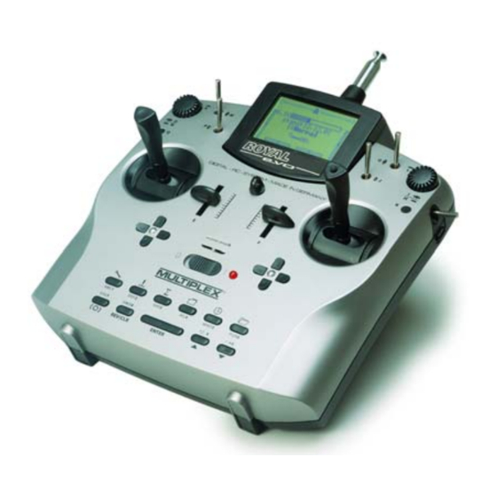
Page 8: The Transmitter
RF signal can be generated, As usual with MPX, the ROYALevo features a MULTIPLEX and the constantly glowing LED alerts you to the fact multi-function socket ƒ (marked “CHARGE” on the that an RF signal is not being transmitted. -
Page 9: Inside The Transmitter
ROYALevo: HFM-4: A simple, low-cost RF module with plug-in crystals for selecting the channel (transmission frequency). Use only genuine MULTIPLEX transmitter crystals! The optional “Channel-Check” power-on guard module can be fitted at any time. HFM-S:... -
Page 10: Adjusting The Transmitter Aerial
RF section. an realigned by the MULTIPLEX service. When operating a model always extend the ae- Removing the RF module: rial to its full length. Only in this configuration... -
Page 11: Changing The Transmitter Crystal (Hfm-4 Module Only)
ROYAL evo When installing the battery ensure that the battery lead ule is to be stored outside the transmitter, it is is correctly positioned, and cannot become jammed or essential to protect it from dirt and damp, and al- snagged when you close the case. -
Page 12: Swivelling The Stick Units
Instructions nuts from the old ones, and use them to secure the new 7.4.8. Swivelling the stick units stick tops (Fig. 2). The stick units of the ROYALevo can be swivelled in their Before installing the stick tops ensure that the stick mountings in order to align them perfectly with your shaft is clean and free of grease and oil. -
Page 13: Installing The Optional Switches "P" And "K
ROYAL evo Tip: Fig. 1 Threading the wires is easier if you slightly bend the wire-ends and hold the stick in one of the corners. Clip the wires in the holders designed for them on the stick unit. Check that the wires have sufficient freedom when the stick is deflected;... -
Page 14: This Is New
For this reason it is only (approx. 1.5% per day). The battery management permissible to replace the battery with another automatically reduces the available charge accord- genuine MULTIPLEX transmitter pack! ingly. Additional safety notes • Batteries are potentially hazardous, and must be stored out of the reach of children. -
Page 15: Charging The Transmitter Battery
Connecting the charger with reversed polarity the charging socket on the back of the transmitter may ruin the battery! (è 7.2.). Use only genuine MULTIPLEX charge (excessive heat, escape of corrosive electrolyte, leads (e.g. transmitter charge lead with banana bursting of cells) plugs # 8 6020). -
Page 16: Using The Transmitter
Instructions screen switches to the last active status display, and the Using the transmitter transmitter is ready to use. The first time you switch the transmitter ON with a syn- 9.1. Switching on for the first time thesizer RF module fitted, or after installing a different When you switch on t h e transmitter for the first time synthesizer RF module, an information screen appears, the following display appears:... -
Page 17: Security Queries When Switching On
ROYAL evo ⇒ You are now at the channel setting menu, 9.3. Security queries when switching ON RF is OFF (LED glows constantly). 9.3.1. Throttle check The following display appears: If in the menu L Transmitter the parameter Check thr. is ON (è 13.1.6.), the following can appear: Set the channel you wish to use by pressing the „s“(UP) -
Page 18: The Status Displays
Instructions monitoring is much safer, as it is also capable of detect- (flight phases) Status display ing faults and errors:: • Is an RF module installed? • Is the connection between RF module and trans- mitter in order (contact fault)? •... -
Page 19: The Basic Operating Philosophy
ROYAL evo Button Function in the Function in The basic operating philosophy status display a menu The ROYALevo features a new, very simple operating REV/CLR Reverse/clear button philosophy which is easy and fast to learn. Proven ele- Cancel or reverse and... -
Page 20: The 3-D Digi-Adjustors
Instructions Note: If you use flight phases 10.2. The 3-D -adjustors digi Setup parameters which have different values for each The transmitter is fitted with two 3-D digi-adjustors as flight phase are displayed correctly, i.e. the displayed standard, and these are used for programming and values vary according to the currently active flight setting up the system phase, and can be adjusted separately in each flight... -
Page 21: Opening Sub-Menus
ROYAL evo SETUP (configuration (è 13.) Transmitter Mixer definiitions Assignment Training Userr CONTROL (è 14.) Access to the individual set-up menus for the To open a sub-menu press the “ENTER” button, or alter- transmitter controls. The screen only displays natively one of the two 3-D digi-adjustors. -
Page 22: Returning From Whence You Came
Instructions Press the ENTER button (or one of the 3-D digi Digital trims adjustors) to release the parameter for changing. With the UP/DOWN buttons s t (or one of the 3- 11.1. Introduction D digi adjustors) you can now select one of the two languages: The ROYALevo features modern digital trims for the 4 primary control axes (stick functions). -
Page 23: The Cruciform Digital Trim Assembly
ROYAL evo 11.3. The cruciform digital trim assembly Creating a new model The trims of the ROYALevo take the form of buttons 12.1. Basic information arranged in a cross, located below and to one side of the stick units. They are located in an ergonomically... -
Page 24: A New Helicopter
Instructions “ “ TIP: Changing the assignment Step Pre-flight checks If the default assignment of transmitter controls and Your newly created model is now ready to fly. Before switches does not meet your requirements, you can you operate the model for the first time be sure to test change the set-up at any time. - Page 25 ROYAL evo Rotor head systems in tamplates TIP: HELImech Model with In the same menu you can also change the assignment mechanical rotor head mixing of the receiver outputs if necessary (in sequence and/or function). Heliccpm Model with electronic rotor head mixing (CCPM);...
- Page 26 Instructions accordance with this default set-up. If your model fea- ” ” Step Setting up the tail rotor mixer tures a different type of swashplate control system, you (static tail rotor compensation / REVO-MIX) will need to alter these values to suit. The tail rotor mixer is set up in the menu G Mixer, TAIL The control travels can now be adjusted in the menu H (è...
- Page 27 ROYAL evo now “released”, and the model is ready to fly. Throttle is • • Step Setting up and testing the gyro controlled by collective pitch via the throttle curve you The model templates are designed to reflect the fact have already set.
-
Page 28: Model Templates In Detail
Instructions venient method of altering values is to use the 3-D digi- a. Check the stick functions (aileron/elevator/rudder); if adjustor (è 10.2.2). necessary select a different mode (è 13.3.1.) L, Assignment, Mode ˜ ˜ Step Activating flight phases b. Check the direction of servo rotation for all functions, Once you have test-flown the model in one flight phase if necessary reverse the directions (REVERSE) (usually the Hover flight phase) and successfully... -
Page 29: Template: Acro
ROYAL evo 12.6. Template: ACRO 12.7. Template: HOTLINER suitable for: suitable for: Power models such as F3A (formerly RC1), F3AX Typical models: Bonito, Akro, Akro Star Fun-fly models 12.7.1. Assigned transmitter controls and switches Typical models: Assignment used: POWER Sky Cat (fig. 12.5.2.) -
Page 30: Template: Delta
Instructions 12.8. Template: DELTA 12.9. Template: GLIDER suitable for: suitable for: Deltas and flying wings powered or glider, Gliders with two wing flaps (i.e. ailerons only), with Model Jets electric power, with V-tail Typical models: Typical models: PiCOJet, TWIN-JET (fig. 12.7.2.), Stuntman Flamingo, Kranich, Alpha 21/27 12.8.1. -
Page 31: Template: 4-Flaps
ROYAL evo 12.10. Template: 4-Flaps 12.11. Template: HELImech suitable for: suitable for: F3B, F3J, Main rotor control systems with mechanical mixers Glider with four wing flaps, with electric power, Typical models: with V-tail Typical models: Ergo, Futura, Moskito, Raptor DG 600, ASW 27, Milan, E... -
Page 32: Template: Heliccpm
Instructions 12.12. Template: HELIccpm Main menu „Setup“ L suitable for: This main menu is primarily concerned with settings Main rotor control systems with electronic mixers which apply to the transmitter generally. CCPM (Cyclic-Collective-Pitch-Mixing) with 3 or 4 servos, 90° to 150° Typical models: 13.1. -
Page 33: Parameter „Battery Charge
Is the THROTTLE control at idle? ployed by the MULTIPLEX PROFI mc 3000 and 4000 The message is displayed as long as the throttle control series of radio control systems. A simple method of... -
Page 34: Defining Mixers
Instructions • The mixer must be assigned to the appropriate 13.2.3. The mixer options receiver outputs (è K Servo, Assignment). ™ „Symmetrical“ • The inputs must be set up correctly, i.e. the magni- tude and direction of the servo’s movements when Neutral position of control: Centre the input / transmitter control is operated... -
Page 35: Sub-Menu "Assignment
Offs+Trv Offs = 0% Application sample: TIP: -100% Input Spoiler in the Control For modellers familiar with the MULTIPLEX PROFI mc Offs Offs 100% travel mixer FLAP+ for large 3000 and 4000: travel down-wards with Offs = -50% butterfly (crow). -
Page 36: Parameter „Mode
Instructions If you attempt to change one of these “standard mixers” 13.3.4. Parameter „Assignment - Controls“ the following on-screen note appears: Affects active assignment only (è13.3.2.) 13.3.1. Parameter „Mode“ The following control functions are available: I Affects active model only Control function Note The transmitter controls for the primary control axes... -
Page 37: Parameter „Assignment - Switches
ROYALevo, Cockpit MM, Commander mc, EUROPA mc, setting the motor (electric or gaso- PiCOline, PROFI mc 3010/3030/4000 line) is switched OFF (è 9.3.1.) Many older MULTIPLEX transmitters can also be used as µ slot Activates slot timer pupil transmitter. If your pupil transmitter is not men- (è17.2.) -
Page 38: The Royalevo As Pupils Transmitter
ROYALevo, Commander mc, PiCOline, using the ROYALevo PC program, and take their place as PROFI mc 3010/3030/4000 the second language. Some older MULTIPLEX transmitters can also be used as 13.5.3. Parameter „Name“ teacher transmitter. If your teacher transmitter is not ü... -
Page 39: Sub-Menus For Individual Controls
ROYAL evo Transmitter control switches are used when you wish to trigger a switched process using a proportional trans- mitter control. Trim display only Aileron Step 0.5/2.5/2.5/3.5% Example: motor run, electric motor Elevator 0% to 100% You wish the sum timer to start running as soon as the... -
Page 40: Parameter „Trim
Instructions the flaps are controlled using a transmitter control (e.g. 14.2.2. Parameter „Trim“ slider F) in the normal way. display only change using cruciform trim buttons one trim value for each flight phase The value of this parameter indicates the extent of the trim for this control, i.e. -
Page 41: Parameter "Throttle" (Throttle Curve)
ROYAL evo Example 2: Coll. pitch curve phase Cruise Throttle curve for Autorot(ation) Autorot(ation) (linear, symmetrical coll. p itch curve for identical reac- The flight phase named Autorot (phase 4 as standard, tions during climb and descend) highest priority) has a fixed throttle position (“safe” idle with open clutch or motor OFF) for the training of auto- rotation landings. -
Page 42: Main Menu „Mixers" G G
Instructions Main menu „Mixers“ G G The Mixers main menu is a dynamic menu, i.e. only those mixers which are used in the current model also appear in this menu. Exception for fixed-wing models: The mixers Combi-Switch and A -Diff (aileron differential) are always present. -
Page 43: Parameter „Mode
ROYAL evo The following table shows the characteristics of the two Mode: Damping gyro systems which are in common use today. Gyro gain is selected using the parameter Damping (Gyro gain). Separate values can be set for each flight Damping gyro Heading-lock gyro phase. -
Page 44: Parameter „Heading / Damping" (Gyro Gain)
Instructions Suppression works in all gyro modes (Transmitter con- 15.3.2. Parameter „Heading / Damping“ trol, Damping, Heading) using the same value, regard- (Gyro gain) less of flight phase. In the gyro mode Control: Exception: Gyro gain can only be adjusted manually using the If gain is in the range 0 ... -
Page 45: Parameter „Collective Pitch+ And
ROYAL evo 15.4.1. Parameter „Collective Pitch+ and -“ 15.5. Sub-menu „Rotor head“ I affects the active model memory (electronic swashplate mixer/CCPM) Separate value for each flight phase Range -100 ... +100% The ROYALevo features a swashplate mixer can be assigned to 3-D digi-adjustor... -
Page 46: Parameter „Geometry
Instructions The radial spacing ratio (centre rotor shaft -> actuation point) of the servo Head f/b is adjusted relative to the 4-point 90° swashplate Example 2: two lateral servos Head le and Head ri in the form of a Geometry -90°... -
Page 47: Sub-Menu „Throttle Compensation
ROYAL evo 15.6. Sub-menu „Throttle compensation“ 15.7. Setting up “free mixers” I affects the active model memory The term “free mixers” means the mixers which are Range 0% to 100% defined in the menu Setup/Mixer (è 13.2). The mixers Default OFF defined there (max. -
Page 48: Main Menu „Servo" K K
Instructions Main menu „Servo“ K Column 1 Shows the mixer option assigned (above input) to the mixer input in the form of a I affects active model memory symbol (è 13.2.3) Column 2+3 Show the type and effect of the mixer values. -
Page 49: Parameter „P1
9 (or 12) servos are shown in the list For example, if the flaps of a multi-flap wing do not mo- As with the MULTIPLEX PROFI mc 3000 and 4000 series ve through exactly the same deflections, the travels can... -
Page 50: Special: Multinaut
Instructions Table for the menu Servo Assignment 16.2.2. Assigning servos for fixed wing models The following transmitter controls / mixers are available, Col. 1 Channel / Servo number depending on the model type (fixed-wing / helicopter): ⇒ max. 9 channels ROYALevo 9 ⇒... -
Page 51: Assigning Servos For Helicopters
ROYAL evo 16.2.3. Assigning servos for helicopters 16.3. Sub-menu „Monitor“ The servo monitor acts as a substitute for a receiving system with servos connected. It enables you check the Model type „Helicopter“ function / response of speed controllers, gyro systems, Note speed regulators etc., and helps to locate errors. -
Page 52: Main Menu „Timer" A A
Instructions Alarm sequence: Main menu „Timer“ A A • 10 seconds before the set alarm time: short beep The ROYALevo has 5 timers. Four of them you will find in every second (æ) the Timer menu A. The fifth timer records the operating •... -
Page 53: Main Menu „Memory" I I
ROYAL evo 18.3. Sub-menu „Erase“ Main menu „Memory“ I When you have selected the memory you wish to erase, The ROYALevo has 20 or 36 model memories, depend- press the 3-D digi-adjustor or the ENTER button. The ing on the version you have purchased. The memory screen displays the security query “Erase selected... -
Page 54: Block / Release Flight Phase
Instructions 18.4.2. Block / release flight phase 18.6. Sub-menu „New model“ Use the REV/CLR button to release or block the flight When you open this sub-menu the following display phases. First select the flight phase, then activate the appears: name, and finally switch between “free” and “blocked” using the REV/CLR button. -
Page 55: Accessories
8 5655 The user can install the scanner. No tools or adjustments Transmitter neckstrap 8 5646 are required. Transmitter Coross-over strap 8 5640 Available frequencies/bands: see MULTIPLEX main cata- Padded neckstrap cushion 8 5641 logue Switch 2-position 7 5748 19.2. Channel-Check Stick top button/switch (è... -
Page 56: Using Multinaut
Each key-press changes (toggles) the status of the Diagnosis lead load. (OFF à ON resp. ON àOFF) for MULTIPLEX switch leads with charge socket # 8 5105 for the „EinStein“ # 8 5162 Right-hand sketch Servo 6 = M.naut 2 a. -
Page 57: Care And Maintenance
If checked regularly by an authorised MULTIPLEX Service nevertheless an unanswered question arises, your local Centre. This should be done every 2 - 3 years, but the dealer will be glad to help you.
Need help?
Do you have a question about the Royal Evo and is the answer not in the manual?
Questions and answers