Advertisement
Available languages
Available languages
Quick Links
TPD1388
OPERATION AND MAINTENANCE MANUAL
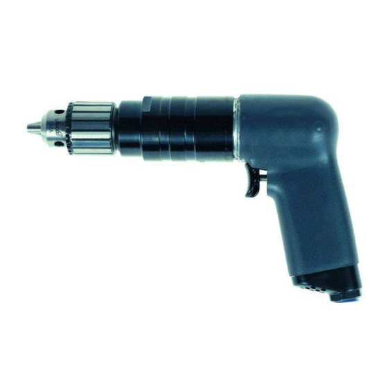
Series 7A Drills are designed for drilling operations in the aerospace, automotive, appliance,
electronic, machining and furniture industries.
Ingersoll–Rand is not responsible for customer modification of tools for applications on which
Ingersoll–Rand was not consulted.
IT IS THE RESPONSIBILITY OF THE EMPLOYER TO PLACE THE INFORMATION
IN THIS MANUAL INTO THE HANDS OF THE OPERATOR.
FAILURE TO OBSERVE THE FOLLOWING WARNINGS COULD RESULT IN INJURY.
PLACING TOOL IN SERVICE
•
Always operate, inspect and maintain this tool in
accordance with American National Standards
Institute Safety Code for Portable Air Tools
(ANSI B186.1).
•
For safety, top performance, and maximum durability
of parts, operate this tool at 90 psig (6.2 bar/620 kPa)
maximum air pressure at the inlet with 5/16" (8 mm)
inside diameter air supply hose.
•
Always turn off the air supply and disconnect the air
supply hose before installing, removing or adjusting
any accessory on this tool, or before performing any
maintenance on this tool.
•
Do not use damaged, frayed or deteriorated air hoses
and fittings.
•
Be sure all hoses and fittings are the correct size and
are tightly secured. See Dwg. TPD905–1 for a typical
piping arrangement.
•
Always use clean, dry air at 90 psig maximum air
pressure. Dust, corrosive fumes and/or excessive
moisture can ruin the motor of an air tool.
•
Do not lubricate tools with flammable or volatile
liquids such as kerosene, diesel or jet fuel.
•
Do not remove any labels. Replace any damaged label.
The use of other than genuine Ingersoll–Rand replacement parts may result in safety hazards, decreased tool performance, and
increased maintenance, and may invalidate all warranties.
Repairs should be made only by authorized trained personnel. Consult your nearest Ingersoll–Rand Authorized Servicenter.
Refer All Communications to the Nearest
Ingersoll–Rand Office or Distributor.
Ingersoll–Rand Company 2000
Printed in U.S.A.
FOR SERIES 7A DRILLS
IMPORTANT SAFETY INFORMATION ENCLOSED.
READ THIS MANUAL BEFORE OPERATING TOOL.
03539731
USING THE TOOL
•
Always wear eye protection when operating or
performing maintenance on this tool.
•
Always wear hearing protection when operating this
tool.
•
Keep hands, loose clothing and long hair away from
rotating end of tool.
•
Anticipate and be alert for sudden changes in motion
during start up and operation of any power tool.
•
Keep body stance balanced and firm. Do not
overreach when operating this tool. High reaction
torques can occur at or below the recommended air
pressure.
•
Tool shaft may continue to rotate briefly after throttle
is released.
•
Air powered tools can vibrate in use. Vibration,
repetitive motions or uncomfortable positions may be
harmful to your hands and arms. Stop using any tool
if discomfort, tingling feeling or pain occurs. Seek
medical advice before resuming use.
•
Use accessories recommended by Ingersoll–Rand.
•
Always use a Dead Handle with Models 7ANST8 and
7AQST8.
•
This tool is not designed for working in explosive
atmospheres.
•
This tool is not insulated against electric shock.
F
Form P7094
Edition 5
E
October, 2000
P
Advertisement

Related Manuals for Ingersoll-Rand 7ADST4


Summary of Contents for Ingersoll-Rand 7ADST4
- Page 1 03539731 Form P7094 Edition 5 October, 2000 TPD1388 OPERATION AND MAINTENANCE MANUAL FOR SERIES 7A DRILLS Series 7A Drills are designed for drilling operations in the aerospace, automotive, appliance, electronic, machining and furniture industries. Ingersoll–Rand is not responsible for customer modification of tools for applications on which Ingersoll–Rand was not consulted.
- Page 2 WARNING LABEL IDENTIFICATION FAILURE TO OBSERVE THE FOLLOWING WARNINGS COULD RESULT IN INJURY. WARNING WARNING WARNING Always turn off the air sup- Always wear eye protection Always wear hearing ply and disconnect the air when operating or perform- protection when operating supply hose before install- ing maintenance on this this tool.
- Page 3 HOW TO ORDER A DRILL DRILL WITH PISTOL GRIP HANDLE Free Speed Chuck Capacity Model 7ADST4 20 000 7AHST4 6 000 7AJST4 4 800 7AJJST4 4 000 7AKST6 3 200 7ALST6 2 400 7AMST6 1 400 7ANST8 7AQST8...
- Page 4 à utiliser l’outil. corrosiveset/ou une humidité excessive peuvent • Utiliser les accessoires recommandés par endommager le moteur d’un outil pneumatique. Ingersoll-Rand. • Ne jamais lubrifier les outils avec des liquides • Utiliser toujours une poignée auxiliaire sur les inflammables ou volatiles tels que le kérosène, le gasol Modèles 7ANST–8 et 7AQST8.
- Page 5 SIGNIFICATION DES ETIQUETTES D’AVERTISSEMENT ATTENTION LE NON RESPECT DES AVERTISSEMENTS SUIVANTS PEUT CAUSER DES BLESSURES ATTENTION ATTENTION ATTENTION Couper toujours l’alimentation Porter toujours une Porter toujours des lunettes d’air comprimé et débrancher le protection acoustique de protection pendant flexible d’alimentation avant pendant l’utilisation de cet l’utilisation et l’entretien de d’installer, déposer ou ajuster...
- Page 6 MISE EN SERVICE DE L’OUTIL SPÉCIFICATIONS Modèle Poignée à Vitesse libre Capacité du levier mandrin tr/mn pouces (Nm) 7ADST4 pistolet 20 000 1/4 (6) 7AHST4 pistolet 6 000 1/4 (6) 7AJST4 pistolet 4 800 1/4 (6) 7AJJST4 pistolet 4 000...
- Page 7 MANUAL DE FUNCIONAMIENTO Y MANTENIMIENTO PARATALADROS MODELOS 7A NOTA Los Taladros Modelo 7A están diseñados para las operaciones de taladro en la industria aeroespacial, del automóvil, electrónica, mecánica y del mueble. Ingersoll–Rand no aceptará responsabilidad alguna por la modificación de las herramientas efectuada por el cliente para las aplicaciones que no hayan sido consultadas con Ingersoll–Rand.
- Page 8 ETIQUETAS DE AVISO AVISO EL HACER CASO OMISO DE LOS AVISOS SIGUIENTES PODRÍA OCASIONAR LESIONES. ADVERTENCIA ADVERTENCIA ADVERTENCIA Cortar siempre el suministro Usar siempre protección ocular Usar siempre protección de aire y desconectar la man- al manejar o realizar opera- para los oídos al manejar guera de suministro de aire ciones de mantenimiento en...
- Page 9 PARA PONER LA HERRAMIENTA EN SERVICIO ESPECIFICACIONES Modelo Tipo de Mango Velocidad Libre Capacidad de Portapuntas pulg. (Nm) 7ADST4 pistola 20 000 1/4 (6) 7AHST4 pistola 6 000 1/4 (6) 7AJST4 pistola 4 800 1/4 (6) 7AJJST4 pistola 4 000...
- Page 10 MANUAL DE FUNCIONAMENTO E MANUTENÇÃO BERBEQUINS SÉRIE 7A AVISO Os Berbequins7A são concebidos para aplicações de perfuração em linhas de montagem, indústrias de equipamentos, eletronicas, aeroespaciais e de mobílias. A Ingersoll–Rand não é responsável por modificações, feitas pelo cliente em ferramentas, nas quais a Ingersoll–Rand não tenha sido consultada.
- Page 11 IDENTIFICAÇÃO DO RÓTULO DE ADVERTÊNCIA ADVERTÊNCIA O NÃO CUMPRIMENTO DAS SEGUINTES ADVERTÊNCIAS PODE RESULTAR EM FERIMENTO. ADVERTÊNCIA ADVERTÊNCIA ADVERTÊNCIA Desligue sempre a alimentação de Use sempre óculos de pro- Use sempre protecção contra ar e desconecte a mangueira de tecção quando estiver ope– alimentação de ar antes de insta- o ruído ao operar esta ferra- rando ou executando algum...
- Page 12 COLOCANDO A FERRAMENTA EM FUNCIONAMENTO ESPECIFICAÇÕES Modelo Tipo de Velocidade Livre Capacidade da Bucha Punho mm (pol.) 7ADST4 pistola 20 000 6 (1/4) 7AHST4 pistola 6 000 6 (1/4) 7AJST4 pistola 4 800 6 (1/4) 7AJJST4 pistola 4 000 6 (1/4)
- Page 13 (Dwg. TPA1365–1)
- Page 14 PART NUMBER FOR ORDERING PART NUMBER FOR ORDERING ♦ Motor Housing Assembly Vane Packet (set of 4 Vanes) ... . 7AH–42A–4 for models ending in EU ..7AH–EU–AST40A Cylinder .
- Page 15 PART NUMBER FOR ORDERING PART NUMBER FOR ORDERING Rotor Pinion Grease Fitting ..... D0F9–879 for H, M or N ratio (22 teeth) ..7AH–17 Spindle Bearing .
- Page 16 MAINTENANCE SECTION 3. Being careful not to distort the Motor Housing (1), grasp the flats on the Housing in leather–covered or copper–covered vise jaws with the Gear Case (38) Always wear eye protection when operating or facing upward. performing maintenance on this tool. 4.
- Page 17 MAINTENANCE SECTION Disassembly of the Motor In the following step, only remove the Throttle 1. Remove the Bearing Housing Spacer (27), Front Valve Seat (5) when replacing it or when the Rotor Bearing Housing (25) and the two Bearing Trigger Bushing (2) must be replaced. Spring Washers (26) from the Motor Housing (1).
- Page 18 MAINTENANCE SECTION Needle Bearing Inserting Tool 5. Insert the Trigger Assembly into the Trigger Bushing so that the hole in the Trigger Pin aligns dead center with the hole in the Throttle Valve Seat. 6. Fold or roll the Muffler Element (13) and work it into the exhaust cavity in the handle of the Motor Housing.
- Page 19 MAINTENANCE SECTION 5. Grasp the splined end of the Rotor in leather–covered 5. Work a small amount of the recommended grease into or copper–covered vise jaws with the short hub of the the gear teeth in the Gear Case. Rotor upward. 6.
-
Page 20: Troubleshooting Guide
MAINTENANCE SECTION TROUBLESHOOTING GUIDE Trouble Probable Cause Solution Loss of Power Low air pressure Check air supply at the Inlet. For top performance, the air pressure must be 90 psig (6.2 bar/620 kPa) at the inlet. Plugged Air Strainer Screen or Clean the Air Strainer or Screen in a clean, Inlet Screen suitable, cleaning solution.
Need help?
Do you have a question about the 7ADST4 and is the answer not in the manual?
Questions and answers