Advertisement
Quick Links
Advertisement

Related Manuals for Ingersoll-Rand 7LN3A44


Summary of Contents for Ingersoll-Rand 7LN3A44
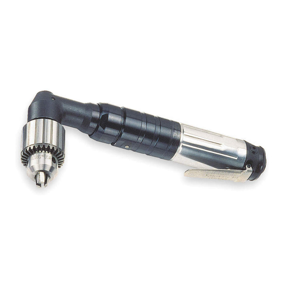
- Page 1 16572638 Edition 2 May 2014 Air Drill 7L Series Maintenance Information Save These Instructions...
- Page 2 Product Safety Information WARNING Failure to observe the following warnings, and to avoid these potentially hazardous situations, could result in death or serious • injury. • Read and understand this and all other supplied manuals before installing, operating, repairing, maintaining, changing accessories on, or working near this product.
- Page 3 11. Grasp the spline of the pinion shaft in leather-covered or copper- Jacking Bolt covered vise jaws and gently tap the rear face of the Angle Head with a soft hammer to pull the Bevel Pinion Bearing. Jacking Nut Disassembly of Gearing Bearing Removal Sleeve 1.
- Page 4 so the inlet is upward. NOTICE 10. Using a wrench on the flats, unscrew and remove the Inlet Bushing (15). Make certain the End Plate Retainer (19) does not fly when it is 11. Remove the Throttle Valve Spring (8) and Air Strainer Screen (16). slipped off the hub of the Rotor.
- Page 5 14. Thread the Inlet Bushing into the Motor Housing, making certain For J or M ratio, press the new Spindle Planet Gear Bearings into the Throttle Valve Spring encircles the short-stem end of the the Spindle Planet Gear to a depth of 0.02” to 0.03” (0.50 mm Throttle Valve.
- Page 6 of 2.12” (54 mm) but not less than 2.11” (53.5 mm) below the end thread-locking compound to the small outside diameter of face of the Angle Head. See Dwg. TPD793. the Upper Spindle Bearing Shaft. Press the Spindle Upper Bearing (105) onto the Spindle (122) and allow the thread-locking compound to dry for a minimum of 10 minutes.
- Page 7 Spindle into the Angle Head until the Spindle Upper Bearing Minimum Dimension Maximum Dimension seats into the recess of the Angle Head. “A” “A” q. Slip the Lower Spindle Bearing, stamped end out, over the end of the Spindle and against the face of the Angle Head. CAUTION 1.21 30.75...
-
Page 8: Troubleshooting Guide
Troubleshooting Guide Trouble Probable Cause Solution Loss of Power Low air pressure Check air supply. For top performance, the air pressure must be 90 psig (6.2 bar/620 kPa) at the inlet. Plugged Air Strainer Screen or Inlet Screen Clean the Air Strainer or Inlet Screen in a clean, suitable, cleaning solution. If the Screen cannot be cleaned, replace it. - Page 9 Notes:...
- Page 10 Notes:...
- Page 11 Notes:...
- Page 12 ingersollrandproducts.com © 2014 Ingersoll Rand...
Need help?
Do you have a question about the 7LN3A44 and is the answer not in the manual?
Questions and answers