
Related Manuals for GORMAN-RUPP VGH Series


Summary of Contents for GORMAN-RUPP VGH Series
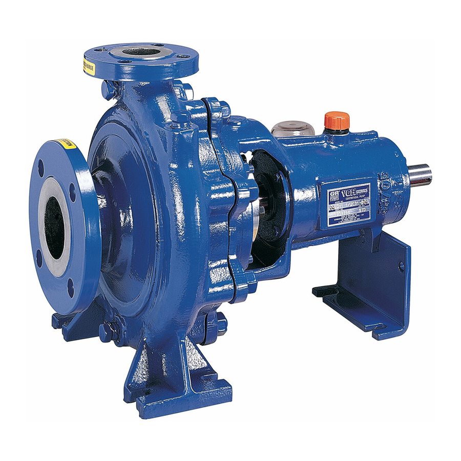
- Page 1 OM‐06114-02 April 16, 2008 Rev. A 09‐20‐16 INSTALLATION, OPERATION, AND MAINTENANCE MANUAL WITH PARTS LIST VGH SERIES PUMP MODEL VGH1 1/4D31-B GORMAN‐RUPP PUMPS www.grpumps.com 2008 Gorman‐Rupp Pumps Printed in U.S.A.
- Page 2 Register your new Gorman‐Rupp pump online at www.grpumps.com Valid serial number and e‐mail address required. RECORD YOUR PUMP MODEL AND SERIAL NUMBER Please record your pump model and serial number in the spaces provided below. Your Gorman‐Rupp distributor needs this information when you require parts or service. Pump Model: Serial Number:...
-
Page 3: Table Of Contents
TABLE OF CONTENTS INTRODUCTION ..........PAGE I - 1 SAFETY ‐... - Page 4 TABLE OF CONTENTS (continued) BEARING TEMPERATURE CHECK ......... . PAGE C - 4 LUBRICATION .
-
Page 5: Introduction
VGH SERIES OM-06114 INTRODUCTION Thank You for purchasing a Gorman‐Rupp pump. HAZARD AND INSTRUCTION Read this manual carefully to learn how to safely DEFINITIONS install and operate your pump. Failure to do so could result in personal injury or damage to the The following are used to alert maintenance per... -
Page 6: Safety - Section A
VGH SERIES OM-06114 SAFETY ‐ SECTION A This information applies to VGH Series trained solids. Only the Gorman‐Rupp Company or an authorized Gorman‐ basic pumps. Gorman‐Rupp has no Rupp distributor may modify a pump or control over or particular knowledge of approve its use for handling volatile, the power source which will be used. - Page 7 OM-06114 VGH SERIES the pump is adequately ventilated. Al closed discharge valve for long periods low the pump to cool and use extreme of time. If operated against a closed dis caution when venting the pump, or charge valve, pump components will...
-
Page 8: Installation - Section B
VGH SERIES OM-06114 INSTALLATION - SECTION B Review all SAFETY information in Section A. e. If the pump has been stored for more than 12 months, some of the components or lubri Since pump installations are seldom identical, this cants may have exceeded their maximum section offers only general recommendations and shelf life. -
Page 9: Mounting
OM-06114 VGH SERIES Mounting tapped, drill and tap the suction and discharge lines not less than 18 inches (457,2 mm) from the suction and discharge ports and install the lines. Locate the pump in an accessible place as close as Installation closer to the pump may result in erratic practical to the liquid being pumped. -
Page 10: Suction Lines In Sumps
VGH SERIES OM-06114 Suction Lines In Sumps of one or both pumps. To avoid this, position the suction inlets so that they are separated by a dis If a single suction line is installed in a sump, it tance equal to at least 3 times the diameter of the should be positioned away from the wall of the suction pipe. -
Page 11: Discharge Lines
OM-06114 VGH SERIES DISCHARGE LINES FILL ONLY THROUGH CONSTANT LEVEL OILER Siphoning Do not terminate the discharge line at a level lower than that of the liquid being pumped unless a si phon breaker is used in the line. Otherwise, a si... -
Page 12: Coupled Drives
VGH SERIES OM-06114 When checking alignment, disconnect the power source to ensure that the pump will remain inoperative. Adjusting the alignment in one direction may alter the alignment in another direc tion. check each procedure after altering Figure 3B. Aligning Non‐Spider Type Couplings alignment. -
Page 13: Electrical Connections
OM-06114 VGH SERIES The electrical power used to operate the pump is high enough to cause injury or death. Obtain the services of a qualified electrician to make all electrical con nections. MISALIGNED: MISALIGNED: ALIGNED: SHAFTS SHAFTS SHAFTS PARALLEL AND... -
Page 14: Operation - Section C
OM-06114 VGH SERIES OPERATION - SECTION C Review all SAFETY information in Section A. PRIMING Install the pump and piping as described in IN Follow the instructions on all tags, labels and de STALLATION. Make sure that the piping connec... -
Page 15: Exhaust Primers
OM-06114 VGH SERIES suction line and pump casing. To prime a pump Auxiliary Ejectors with a hand vacuum pump, open the cock on the Ejectors function much like exhaust primers. They pump priming line. Operate the hand pump until may be operated by steam, compressed air, water liquid flows out of the check valve on the bottom of or exhaust gases. -
Page 16: Operation
OM-06114 VGH SERIES If overheating does occur, stop the pump immedi OPERATION ately and allow it to cool before servicing it. Ap proach any overheated pump cautiously. Strainer Check Pump speed and operating points must be If a suction strainer has been shipped with the... -
Page 17: Stopping
OM-06114 VGH SERIES BEARING TEMPERATURE CHECK Bearings normally run at higher than ambient tem peratures because of heat generated by friction. To avoid serious damage to the pump, Temperatures up to 160_F (71_ C) are considered check for unusual noises or excessive vi... -
Page 18: Bearings
OM-06114 VGH SERIES uid from an external source. When handling clean the oil more frequently if the pump is operated con liquids, flushing liquid is taken from the pump dis tinuously or installed in an environment with rapid charge and supplied through the seal flush line temperature change. -
Page 19: Troubleshooting - Section D
VGH SERIES OM-06114 TROUBLESHOOTING - SECTION B Review all SAFETY information in Section A. Before attempting to open or service the pump: 1. Familiarize yourself with this manual. 2. Lock out or disconnect the power source and take the necessary pre... - Page 20 OM-06114 VGH SERIES Table D‐1 Troubleshooting Chart (Continued) TROUBLE POSSIBLE CAUSE PROBABLE REMEDY PUMP STOPS OR FAILS Impeller or other wearing parts worn Replace worn or damaged parts. TO DELIVER RATED or damaged. Check that impeller is properly cen FLOW OR PRESSURE tered and rotates freely.
-
Page 21: Preventive Maintenance
VGH SERIES OM-06114 Table D‐1 Troubleshooting Chart (Continued) TROUBLE POSSIBLE CAUSE PROBABLE REMEDY BEARINGS RUN TOO Bearing temperature is high, but Check bearing temperature regularly within limits. to monitor any increase Low or incorrect lubricant. Check for proper type and level of lu... - Page 22 OM-06114 VGH SERIES Preventive Maintenance Schedule Service Interval* Item Daily Weekly Monthly Semi‐ Annually Annually General Condition (Temperature, Unusual Noises or Vibrations, Cracks, Leaks, Loose Hardware, Etc.) Pump Performance (Gauges, Speed, Flow) Bearing Lubrication Seal Lubrication (And Packing Adjustment, If So Equipped) V‐Belts (If So Equipped)
-
Page 23: Pump Maintenance And Repair - Section E
VGH SERIES OM-06114 PUMP MAINTENANCE AND REPAIR ‐ SECTION E MAINTENANCE AND REPAIR OF THE WEARING PARTS OF THE PUMP WILL MAINTAIN PEAK OPERATING PERFORMANCE. STANDARD PERFORMANCES FOR PUMP MODEL VGH1 1/4D31-B Based on 70_ F (21_ C) clear water at sea level Contact the Gorman‐Rupp Company to verify per... - Page 24 OM-06114 VGH SERIES SECTION DRAWING PARTS PAGE Figure 1. Pump Assembly VGH1 1/4D31-B PAGE E - 2 MAINTENANCE & REPAIR...
-
Page 25: Parts List
VGH SERIES OM-06114 PARTS LIST Pump Assembly VGH1 1/4D31-B (From S/N 1379872 Up) If your pump serial number is followed by an “N”, your pump is NOT a standard production model. Contact the Gorman‐Rupp Company to verify part numbers. ITEM... -
Page 26: Pump And Seal Disassembly And Reassembly
OM-06114 VGH SERIES PUMP AND SEAL DISASSEMBLY 4. Check the temperature before opening any covers, plates, or AND REASSEMBLY plugs. 5. Close the suction and discharge Review all Safety information in Section A. valves. 6. Vent the pump slowly and cau... -
Page 27: Wear Ring Removal
VGH SERIES OM-06114 Disconnect the bypass pipe (8) at the couplings (5) Unscrew the pin (11) and press the stationary seal in the pump casing and seal flange (37). seat and O‐ring out of the seal flange. If no further disassembly is required, see Seal Remove the hardware securing the pump casing Installation. -
Page 28: Shaft And Bearing Reassembly And Installation
OM-06114 VGH SERIES outboard bearing (19) from the shaft. Remove the Shaft and Bearing Reassembly And Installation inboard bearing spacer (21). Clean and inspect the bearings as indicated in Shaft and Bearing Removal and Disassembly. After removing the shaft and bearings, clean and inspect the bearings as follows. -
Page 29: Wear Ring Installation
VGH SERIES OM-06114 race, rollers, balls, or ball cage. Press only on the inner race. If heating the bearings is not practical, use a suit The throat bushing must seat squarely in ably sized sleeve and an arbor (or hydraulic) press the seal plate bore;... - Page 30 OM-06114 VGH SERIES Do not attempt to separate the seal, this could damage the seal. Individual parts are not sold sep arately. Inspect the seal for wear, scoring, grooves, and A new seal assembly should be installed other damage that might cause leakage. If any any time the old seal is removed from the components are worn, replace the seal.
-
Page 31: Impeller And Pump Casing Installation
VGH SERIES OM-06114 Lubricate the stationary seat O‐ring with water or Install the casing gasket (41). Slide the pump cas light oil and install it on the O.D. of the stationary ing (1) over the impeller and secure it to the seal seat. - Page 32 OM-06114 VGH SERIES FILL ONLY THROUGH CONSTANT LEVEL OILER Monitor the condition of the bearing lubri cant regularly for evidence of rust or mois ture condensation. This is especially im portant in areas where variable hot and cold temperatures are common.
- Page 33 For Warranty Information, Please Visit www.grpumps.com/warranty or call: U.S.: 419-755-1280 Canada: 519-631-2870 International: +1-419-755-1352 GORMAN‐RUPP PUMPS...
Need help?
Do you have a question about the VGH Series and is the answer not in the manual?
Questions and answers