DRAKE DSE24A Instruction Manual
Digital signage mpeg-2 encoder with qam output
Hide thumbs
Also See for DSE24A:
- Instruction manual (24 pages) ,
- Instruction manual (32 pages) ,
- Instruction manual (32 pages)
Table of Contents
Advertisement
Quick Links
Advertisement
Table of Contents

Related Manuals for DRAKE DSE24A


Summary of Contents for DRAKE DSE24A
- Page 1 Digital Signage MPEG-2 Encoder with QAM Output INSTRUCTION MANUAL Model Item # Description DSE24A 1002571A Digital Signage MPEG-2 Encoder with QAM Output DSE24A Rack Panel 1002565A Rack Mount Panel for (2) DSE24A Encoders © 2017 R.L. Drake Holdings, LLC. Rev: 062817 / 651237500C...
- Page 2 Rev. C: Manual adds support for custom video and transport stream bit rate settings. (firmware v1.0.1) Rev B: Manual adds cross link cable to Installation & Setup – Unpacking on page 10. Rev A: First User Manual for DSE24A Encoder. (firmware v0.9.0.0)
-
Page 3: Table Of Contents
Table of Contents GENERAL & SAFETY INFORMATION SAFETY INSTRUCTIONS & CAUTION STATEMENTS ......................4 GENERAL DESCRIPTION & FEATURES ..........................6 SPECIFICATIONS ..................................7 FRONT AND REAR PANEL OPERATION ..........................8 INSTALLATION & SETUP INSTALLATION & POWER-UP ............................... 10 COMMUNICATING WITH THE UNIT ............................. 11 UNIT CONFIGURATION ACCESSING THE UNIT VIA WEB BROWSER ........................ - Page 4 Important Safety Instructions 1. Read Instructions—All the safety and operating instructions should be read before the product, be sure the antenna or cable system is grounded so as to provide some protection product is operated. against voltage surges and built-up static charges. Article 810 of the National Electrical Code, ANSI/NFPA 70, provides information with regard to proper grounding of the mast and sup- 2.
-
Page 5: General Description & Features
General Description & Features INTRODUCTION The DSE24A is a single channel HD encoder with RF QAM and IP outputs. Drake’s DSE24A encodes an uncompressed video source from devices with HDMI, high-resolution component, composite or VGA outputs. The DSE24A encodes the incoming video to MPEG2. It is then internally connected to a QAM modulator and low-noise upconverter. -
Page 6: Specifications
Specifications DSE24A Digital Signage MPEG-2 Encoder with QAM Output Item # 1002571A INPUT OUTPUT Component RF QAM Connector(s): 3x RCA for Video (Y, Pb, Pr) Connector(s): 1x “F” Female (Rear-panel) Video Resolution: 480i, 720p, & 1080i Modulation: QAM 16, 32, 64, 128, and 256 Video Aspect Ratio: 4:3 &... -
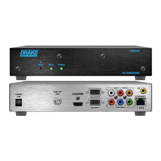
Page 7: Front And Rear Panel Operation
Front and Rear Panel Operation FRONT PANEL VIEW: FRONT PANEL DESCRIPTION IP Reset: When pressed for >10 seconds, the IP address of the control port will be enabled to the default factory IP address (172.16.70.1, Subnet Mask 255.255.0.0). The login credentials will also be enabled to the default username Admin and password pass, which are both case-sensitive. - Page 8 QAM RF Output: "F" Connector for QAM Output. HDMI: HDMI connector for unencrypted HDMI input. The DSE24A does not accept HDCP-Encrypted HDMI Input. VGA Output: DE-15 female connector for loop-through VGA output. VGA Input: DE-15 female connector for VGA input.
-
Page 9: Installation & Setup
• Cross Link Cable, 7 Ft (Item: 515102875 A) Installation The DSE24A encoder is designed for a desk/table top installation. An optional rack panel (stk#1002565A) allows two encoders to be mounted in a 1RU. You can mount the chassis in a standard EIA, 24 inch (610 mm) deep, enclosed rack. Secure the rack chassis front panel to the rack by inserting four machine screws, with cup washers, through the four mounting holes in the front panel. -
Page 10: Communicating With The Unit
Installation & Setup To begin setup, connect the appropriate input and output video cables and plug in the DSE24A power cable. ETHERNET ACCESS: Local or remote communication with the unit is only possible through a GUI-based menu via any standard web browser. -
Page 11: Unit Configuration
Unit Configuration Accessing the Unit via the Web Browser The user must complete the steps described in "Installation & Setup" before proceeding as follows: Open a web browser on your computer (Chrome, Firefox, and IE7+ are recommended) and enter the following URL address (http://172.16.70.1). -
Page 12: Main Tab
Unit Configuration Main Tab: Status Screen The “Main Tab: Status" sub-tab (Figure 2) is a “read only” screen and displays the following information: Figure 2 - Main Tab: Status Screen In the section entitled "TS" under the orange header, the following parameters about the output are displayed: TS: indicates the selected program's information. -
Page 13: Video Screen
Unit Configuration Main Tab: Video Screen The “Main Tab: Video” sub-tab (Figure 3) is a “user-configurable” screen to select the video encoder parameters for the input program. Figure 3 - Main Tab: Video Screen Source: allows the user to select the type of video input source. Options are: Composite, Component, VGA, and HDMI. Bitrate: user must enter the bitrate for the input video. -
Page 14: Audio Screen
Unit Configuration Main Tab: Audio Screen The “Main Tab: Audio” sub-tab (Figure 4) is a “user-configurable” screen where the following parameters associated with the Dolby® Digital encoded stereo audio are configured and displayed for the audio input under a green header: Figure 4 - Main Tab: Audio Screen Source: allows the user to select the type of audio input source. -
Page 15: Ts Config Screen
Unit Configuration Main Tab: Audio Screen (continued) RF Mode: allows the user to select the type of Dynamic Range Compression to be applied to signals that will be used for retransmission on an RF carrier, and fed into a TV tuner or other receive device(s). (Factory Default: “None”) Options for are: i) None: no dynamic range controls have been assigned. - Page 16 Unit Configuration Main Tab: TS Configuration Screen (continued) TS Bitrate: User must enter in the bitrate for the output TS. Options are 19.39 Mbps, 38.8 Mbps (default) and Custom. The Custom TS bitrate can be set from a minimum of the sum of the video and audio bitrates plus TS overhead to a maximum of 38.81070 Mbps.
-
Page 17: Ip Screen
Unit Configuration Main Tab: IP Screen The “Main Tab: IP" sub-tab (Figure 6) is a “read and write” screen to assign IP parameters for the TS: Figure 6 - “Main Tab” IP Screen Destination IP: allows user to assign the IP address of the equipment to which the IP output is streamed to. (Factory Default: "192.168.253.2") The Destination IP Address must be present before streaming occurs, otherwise the session is aborted. -
Page 18: Qam Screen
Unit Configuration Main Tab: QAM Screen The “Main Tab: QAM" sub-tab (Figure 7) is a “read and write” screen to assign QAM parameters for the TS: Figure 7 - Main Tab: QAM Screen Output Channel/Frequency: user must assign an RF channel number to the RF QAM output of the QAM module (i.e. -
Page 19: Output Screen
Unit Configuration Main Tab: Output Screen The “Main Tab: Output" sub-tab (Figure 8) is a “read and write” screen to assign the TS to desired IP, QAM, and ASI outputs: Figure 8 - Main Tab: Output Screen In the section entitled "TS" under the orange header, the following parameters about the TS are displayed: TS Mapping: indicates the program assigned to the TS. -
Page 20: Refresh Tab
Unit Configuration Main Tab: Refresh Tab The "Main Tab: Refresh Tab" can be clicked while you are on any of the following sub-tabs screens: "Status", "Video", "Audio", "TS Config", "IP", "QAM", and "Output". When clicked, it will update all relevant fields/ parameters of the active screen as that information is retrieved from the unit in a real time basis. -
Page 21: Admin Tab
Admin Tab Admin Tab Screen The "Admin Tab" (Figure 10) is a "read and write" screen where the following parameters are displayed and configured: Figure 10 - Admin Tab Screen Login: is the Administrator’s login (10 characters maximum). This login allows the user to make changes to any area of the unit. - Page 22 Admin Tab Admin Tab Screen (continued) New Password: used only if the user wants to change the current Administrator’s password. Must enter a new password (10 characters maximum). Password is case sensitive and will not be displayed. Confirm New Password: user must enter the same password as entered in above.
- Page 23 Admin Tab Admin Tab Screen (continued) Time Server IP: is the IP address for the Time Server from where the unit can obtain its clock reference (see the "Time Tab" section for details). (Factory Default: "172.16.70.2") Syslog Errors: is to enable/disable the unit to forward error messages (in red font) to syslog. (Factory Default: "Disabled") Syslog Informational: is to enable/disable the unit to forward information messages (in blue font) to syslog.
-
Page 24: Time Tab
Time Tab Time Tab Screen The “Time Tab" (Figure 11) is a “read and write” screen tthat allows the user to set the current date and time for the unit. To remain compliant with ATSC and cable standards, it is important to have the accurate date and time stamps. For this reason, it is recommended to use the "NTP Server"... -
Page 25: Event Log Tab
Event Log Tab Event Log Tab Screen The "Event Log Tab" (Figure 12) is a "read and write" screen where the following parameters are displayed or configured. The data in Event Log can be forwarded to a SysLog database – (see , &... -
Page 26: Appendix
Appendix Appendix A: Viewing IP Output on VLC Media Player To view the IP output from the unit on a VLC Media player in a computer or laptop. The procedure is divided into two steps: Step 1: Change the IP address of the computer Step 2: Using the VLC Media Player ( http://www.videolan.org/ ) NOTE: Step 1 needs to be followed only if a unicast IP address is assigned in the “Destination IP”... -
Page 27: Service
Please perform whatever steps are applicable from the product’s Instruction Manual before calling or writing as this could save unnecessary phone charges. Please do not return the product without calling Drake Service and following the steps above first;... -
Page 28: Warranty
Blonder Tongue Laboratories, Inc. Limited Warranty Limited Warranty Blonder Tongue Laboratories, Inc. (BT) will at its sole option, either repair or replace (with a new or factory reconditioned product, Seller will at its sole option, either repair or replace (with a new or factory reconditioned product, as Seller may determin e) any product manufactured or sold (or in as BT may determine) any product manufactured by BT which proves to be defective in materials or workmanship or fails to Blonder Tongue Laboratories, Inc.
Need help?
Do you have a question about the DSE24A and is the answer not in the manual?
Questions and answers