Table of Contents
Advertisement
model no. 052-0726-0
Read and understand this instruction manual thoroughly before
using the product. It contains important information for your
safety as well as operating and maintenance advice.
Keep this instruction manual for future use. Should this product
be passed on to a third party, then this instruction manual must
be included.
SMART
MULTIMETER
INSTRUCTION
MANUAL
Advertisement
Table of Contents

Related Manuals for MasterCraft 052-0726-0


Summary of Contents for MasterCraft 052-0726-0
- Page 1 052-0726-0 SMART MULTIMETER Read and understand this instruction manual thoroughly before INSTRUCTION using the product. It contains important information for your safety as well as operating and maintenance advice. MANUAL Keep this instruction manual for future use. Should this product be passed on to a third party, then this instruction manual must be included.
- Page 2 SMART MULTIMETER 052-0726-0...
-
Page 3: Safety Information
SAFETY INFORMATION The multimeter has been designed according to IEC 61010 concern- ing electronic measuring instruments with a measurement category (CAT III 600V) and pollution degree 2. WARNING To avoid possible electric shock or personal injury, follow these guidelines: Do not use the meter if it is damaged. Before you use the ●... - Page 4 052-0726-0 | contact us 1-800-689-9928 When using the probes, keep your fingers behind the finger ● guards on the probes. When making connections, connect the black test lead before ● you connect the red test lead. When you disconnect test leads, disconnect the red test lead first.
- Page 5 CAUTION To avoid possible damage to the meter or to the equipment under test, follow these guidelines: Disconnect circuit power and discharge all capacitors before ● testing resistance, capacitance or continuity. Use the proper function for your measurements. ● Before pressing the "SELECT" key to change function, disconnect ●...
-
Page 6: Electrical Symbols
052-0726-0 | contact us 1-800-689-9928 ELECTRICAL SYMBOLS Alternating current Direct current Caution, risk of danger. Refer to the operating manual before use. Caution, risk of electric shock. Earth (ground) terminal Conforms to European Union directives The equipment is protected throughout by double insulation or reinforced insulation. -
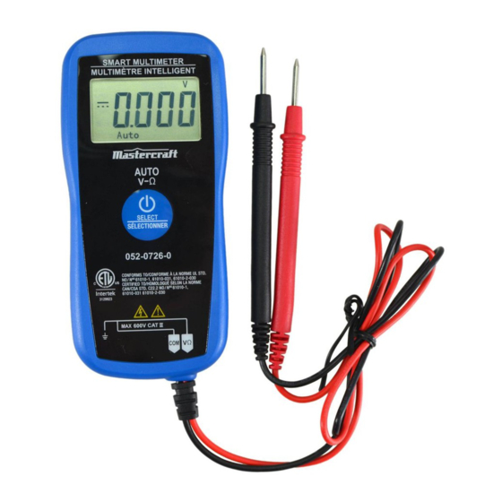
Page 7: Front Panel
FRONT PANEL Display 3 5/6-digit LCD, with a max. reading of 5999. "SELECT" Key Used to select desired function or mode as well as to turn on or off the meter. Test Probes Figure 1 GENERAL SPECIFICATION: 3 5/6-digit LCD, with a max. reading of 5999. Negative Polarity Indication: Negative sign "... -
Page 8: Specifications
052-0726-0 | contact us 1-800-689-9928 SPECIFICATIONS Readings are accurate for a period of 1 year after calibration at 64 to 82ºF (18 to 28ºC), with relative humidity up to 75%. Accuracy specifications take the form of: ± [(% of Reading) + (Number of Least Significant Digits)]... - Page 9 AC VOLTAGE RANGE RESOLUTION ACCURACY 0.001 V 60 V 0.01 V ±(1.0% + 5) 600 V 0.1 V Input Impedance: 10 MΩ Frequency Range: 40 – 400 Hz Max. Allowable Input Voltage: 600 V Response: Average, calibrated in RMS of sine wave Note: In Auto Check mode, the minimum input AC voltage required for AC voltage measurement is 1.5 V.
- Page 10 052-0726-0 | contact us 1-800-689-9928 FREQUENCY RANGE RESOLUTION ACCURACY 10 Hz 0.001 Hz 100 Hz 0.01 Hz 1 kHz 0.1 Hz ±(1.0% + 4 ) 10 kHz 0.001 kHz 100 kHz 0.01 kHz Input Voltage: 1 – 20 V RMS Measurement Range: 1 Hz –...
-
Page 11: Continuity Test
CONTINUITY TEST RANGE RESOLUTION ACCURACY If the resistance is less than about 50 Ω, the built-in buzzer will sound continuously and the display will change from " " to " ". If the resistance is more than 150 Ω, the buzzer will not Open Circuit Voltage: sound and the display will about 0.7 V... -
Page 12: Operating Instructions
052-0726-0 | contact us 1-800-689-9928 OPERATING INSTRUCTIONS Instruction for the "SELECT" Key Press and hold down the "SELECT" key for about 3 secs to turn on the meter. The meter enters Auto Check mode. In Auto Check mode, press the "SELECT" key to step through the functions: Auto Check mode (default) →... - Page 13 AUTO CHECK MODE In Auto Check mode, the meter automatically selects measurement function of DC voltage, AC voltage or resistance based on the input via the test leads. With no input, the display shows " ". With no voltage signal, but a resistance below 10 MΩ present, the meter displays the resistance value.
- Page 14 052-0726-0 | contact us 1-800-689-9928 CONTINUITY TEST FUNCTION In Auto Check mode, press the "SELECT" key once to select continu- ity test function. Connect the test leads across the circuit to be tested. If the resistance is more than 150 Ω, the built-in buzzer will not sound, and the display will show "...
- Page 15 NON-CONTACT AC VOLTAGE DETECTION In Auto Check mode, press the "SELECT" key twice. The built-in buzzer sounds beeps, and the four bar-graph segments, which will be are used to indicate the intensity of electrical field, appear sequentially at the centre of the display from left to right of the display (Figure 2).
- Page 16 052-0726-0 | contact us 1-800-689-9928 NOTE: Detection Range: 50 – 600 V Frequency Response: 50/60 Hz The left top corner of the meter (marked "EF" at the rear of the meter) is the optimum position of the meter for non-contact AC voltage detections.
- Page 17 NOTE: Measurement Range: 0 – 600 V AC To avoid personal electric shock and damage to the meter, do not connect the meter to a voltage higher than 600 V. When the input voltage is ≥ 610 V, the built-in buzzer will sound beeps and the display will show "OL".
- Page 18 052-0726-0 | contact us 1-800-689-9928 RESISTANCE MEASUREMENT FUNCTION In Auto Check mode, press the "SELECT" key five times to select resistance measurement function. The display will show resistance measurement unit. Connect the test leads across the object to be tested. Wait until the reading is stable, then read the resistance reading on the display.
- Page 19 FREQUENCY MEASUREMENT FUNCTION In Auto Check mode, press the "SELECT" key six times to select frequency measurement function, the display will show frequency measurement unit. Connect the test leads across the source or circuit to be tested. Read the frequency reading on the display. NOTE: Input Voltage Range: 1 –...
- Page 20 052-0726-0 | contact us 1-800-689-9928 NOTE: Measurement Range: 1 nF – 100 μF. Because the meter measures capacitance by measuring the time of charging and discharging the capacitor, measuring a higher capacitance will take more time. Automatic Power-Off The meter will turn off automatically if you have not operated the meter for about 15 minutes.
- Page 21 MAINTENANCE Except replacing button cells, never attempt to repair or service the meter unless you are qualified to do so and have the relevant calibration, performance test, and service instructions. Periodically wipe the case with a damp cloth and mild detergent. Do not use abrasives or solvents.
- Page 22 052-0726-0 | contact us 1-800-689-9928 WARRANTY This Mastercraft product carries a one-year warranty against defects in workmanship and materials. This product is not guaranteed against wear, breakage or misuse. DISPOSAL OF THIS ARTICLE Dear Customer, If you at some point intend to dispose of this article,...
Need help?
Do you have a question about the 052-0726-0 and is the answer not in the manual?
Questions and answers
How do I test a wire do direct current