Table of Contents
Advertisement
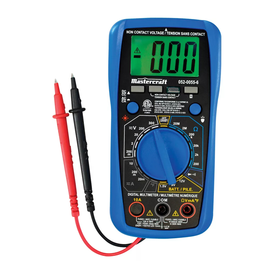
model no. 052-0055-6
Read and understand this instruction manual thoroughly
before using the product. It contains important
information for your safety as well as operating and
maintenance advice.
Keep this instruction manual for future use. Should this
product be passed on to a third party, then this
instruction manual must be included.
MANUAL
DIGITAL MULTIMETER
INSTRUCTION
MANUAL
Advertisement
Table of Contents

Related Manuals for MasterCraft 052-0055-6


Summary of Contents for MasterCraft 052-0055-6
-
Page 1: Digital Multimeter
052-0055-6 MANUAL DIGITAL MULTIMETER Read and understand this instruction manual thoroughly before using the product. It contains important INSTRUCTION information for your safety as well as operating and maintenance advice. MANUAL Keep this instruction manual for future use. Should this product be passed on to a third party, then this instruction manual must be included. -
Page 3: Safety Information
SAFETY INFORMATION This meter has been designed according to IEC 61010 concerning electronic measuring instruments with a measurement category (CAT III 300V) and pollution degree 2. WARNING To avoid possible electric shock or personal injury, follow these guidelines: Do not use the meter if it is damaged. Before you use the meter, ●... - Page 4 052-0055-6 | contact us 1-800-689-9928 Use caution when working with voltage above 30 V AC RMS, ● 42 V peak, or 60 V DC. Such voltages pose a shock hazard. When using the probes, keep your fingers behind the finger ●...
- Page 5 ● CAT III - Measurement Category III is for measurements performed in building installation. Examples are measurements on distribution boards, circuit breakers, wiring, including cables, bus-bars, junction boxes, switches, socket-outlets in the fixed installation, and equipment for industrial use and some other equipment, for example, stationary motors with permanent connection to the fixed installation.
-
Page 6: Electrical Symbols
052-0055-6 | contact us 1-800-689-9928 CAUTION To avoid possible damage to the meter or to the equipment under test, follow these guidelines: Disconnect circuit power and discharge all capacitors thorough- ● ly before testing resistance, diode, continuity or temperature. -
Page 7: Front Panel
INTRODUCTION This meter is a compact 3 1/2-digit digital multimeter designed to measure DC and AC voltage, DC and AC current, resistance, continuity, diode, battery and temperature. In addition, non-contact AC voltage detection, live AC wire detection and illumination functions are also provided. - Page 8 052-0055-6 | contact us 1-800-689-9928 Display 3 1/2-digit LCD, with a max. reading of 1999. "AC/DC" Button Used to switch between DC and AC functions. AC Voltage Detection Button Backlight Button Press this button to turn on or off the backlight. The backlight will turn off automatically about 30 secs after it is turned on.
-
Page 9: General Specifications
"H" Button Used to enter/exit Data Hold mode. Holster Illumination Lamp GENERAL SPECIFICATIONS Display: 3 1/2-digit LCD, with a max. reading of 1999 Negative Polarity Indication: Negative sign " - " shown on the display automatically Sampling Rate: About 2–3 times/sec IP Degree: IP20 Battery: 9 V battery, 6F22 or equivalent, 1 pieces Low Battery Indication: "... -
Page 10: Overrange Indication
052-0055-6 | contact us 1-800-689-9928 DC VOLTAGE OVERRANGE RANGE RESOLUTION ACCURACY INDICATION 200 mV 100 μV ±(0.5% + 5) 1 mV "OL" shown 20 V 10 mV ±(0.8% + 5) on the display 200 V 100 mV 300 V ±(1.0% + 5) - Page 11 DC CURRENT OVERRANGE RANGE RESOLUTION ACCURACY INDICATION 20 mA 10 μA ±(1.0% + 5) "OL" shown on the display 200 mA 100 μA ±(1.5% + 5) 10 A 10 mA ±(2.0% + 5) ——— [ 1 ] Overload Protection: 250 mA/300 V FAST Fuse (for "ΩVmA°F" terminal inputs) 10 A/300 V FAST Fuse (for "10A"...
- Page 12 052-0055-6 | contact us 1-800-689-9928 Overload Protection: 250 mA/300 V FAST Fuse (for "ΩVmA°F" terminal inputs) 10 A/300V FAST Fuse (for "10A" terminal inputs) Max. Allowable Input Current: 10A (For inputs > 2 A: measurement duration < 10 secs, and interval >...
-
Page 13: Resolution Accuracy
TEMPERATURE OVERRANGE RANGE RESOLUTION ACCURACY INDICATION ±(1.0% + 5) 32 to 752ºF (0 to 385ºC) ±(2.5% + 10) ——— [ 1 ] 1ºF (0.6ºC) 752 to 1832ºF (385 to 1000ºC) [ 1 ] If the temperature being measured is out of the range of 32 to 1832ºF (0 to 1000ºC) the display may show a reading, but the measurement error may be large or the thermocouple may be damaged. -
Page 14: Diode And Continuity Test
052-0055-6 | contact us 1-800-689-9928 DIODE AND CONTINUITY TEST RANGE DESCRIPTION TEST CURRENT Open Circuit Voltage: The approx. forward voltage drop about 2.8 V of the diode will be displayed. Test Current: about 1 mA The built-in buzzer will sound if the resistance is less than about 20 Ω. -
Page 15: Measuring Dc Or Ac Voltage
MEASURING DC OR AC VOLTAGE Connect the black test lead to the "COM" terminal and the red test lead to the "ΩVmA°F" terminal. Set the range switch to desired V range position. If the magnitude of the voltage to be measured is not known beforehand, set the range switch to the highest range first and then reduce it range by range until satisfactory resolution is obtained. -
Page 16: Measuring Resistance
052-0055-6 | contact us 1-800-689-9928 Note: If the magnitude of the current to be measured is not known beforehand, set the range switch to the highest range first and then reduce it range by range until satisfactory resolution is obtained. -
Page 17: Diode Test
Note: Before test, disconnect all power to the circuit to be tested and discharge all capacitors thoroughly. DIODE TEST Connect the black test lead to the "COM" terminal and the red test lead to the "ΩVmA°F" terminal. (Note: The polarity of the red lead is positive " + ") Set the range switch to position. -
Page 18: Measuring Temperature
052-0055-6 | contact us 1-800-689-9928 MEASURING TEMPERATURE Note To avoid possible damage to the meter or other equipment, remember that while the meter is rated for 32 to 1832ºF (0 to 1000ºC), the K type thermocouple provided with the meter is rated to 482°F (250°C). -
Page 19: Non-Contact Ac Voltage Detection
NON-CONTACT AC VOLTAGE DETECTION Press and hold down the AC Voltage Detection Button and move the top of the meter close to the object to be tested. When the meter detects AC voltage, the built-in buzzer will sound discontinuously and the AC Voltage Detection Indicator will flash. -
Page 20: Maintenance
052-0055-6 | contact us 1-800-689-9928 Note: To avoid electric shock, do not touch any naked conductor with hand or skin. Because of the meter's detection limit, a line (or conductor) under test may be live even if the buzzer does not sound and the AC Voltage Detection Indicator does not light. -
Page 21: General Maintenance
GENERAL MAINTENANCE Periodically wipe the case with damp cloth and a little mild detergent. Do not use abrasives or solvents. Dirt or moisture in the terminals can affect readings. Clean the terminals as follows: Set the range switch to OFF position and remove all test leads from the meter. - Page 22 052-0055-6 | contact us 1-800-689-9928 When the symbol " " appears on the display, the battery is low and must be replaced immediately. To replace the battery, remove the holster from the meter. Then remove the screw on the battery cover and remove the battery cover.
-
Page 23: Warranty
The contents of this manual can not be used as the reason to use the meter for any special application. WARRANTY This Mastercraft product carries a one-year warranty against defects in workmanship and materials. This product is not guaranteed against wear, breakage or misuse.
Need help?
Do you have a question about the 052-0055-6 and is the answer not in the manual?
Questions and answers
when trying to measure voltage of car battery it shows -1 the wires in right position and internal battery has charge
If the MasterCraft 052-0055-6 meter shows a voltage reading of -1 despite correct wire positioning and a charged battery, it likely indicates a polarity reversal. This means the red and black test leads are connected to the opposite terminals—red to negative and black to positive—causing the meter to display a negative value.
This answer is automatically generated
Lorsque je suis sur continuité pour vérifier un fusible le buzer émet un son en continu
If the buzzer continuously sounds while checking a fuse on a MasterCraft 052-0055-6, it indicates continuity, meaning the fuse is good and not blown.
This answer is automatically generated
when i select continuity it starts to beep continuously without even touching and wires or even if the leads are removed from the unit...
Can we donwnload the full pdf mastercraft 052-0055-6