Advertisement
Table of Contents
- 1 Overview
- 2 Parts List
- 3 Safety Instructions
- 4 Resistance (Ω)
- 5 Ac Current Measurment
- 6 Resistance Measurment
- 7 Diode Test
- 8 Transistor Test/Continuity Check
- 9 Capacitance/Frequency Measurements
- 10 Duty-Cycle/Temperature/Relative Value Measurements
- 11 Replacing Battery/Changing Fuses
- Download this manual
®
Auto-ranging
Digital Multimeter
52-0052-2
INSTRUCTION MANUAL
WARNING: READ AND UNDERSTAND THIS MANUAL BEFORE USING YOUR MULTIMETER. FAILURE TO UNDERSTAND AND COMPLY WITH WARNINGS AND OPERATING INSTRUCTIONS
CAN RESULT IN SERIOUS OR FATAL INJURIES AND/OR PROPERTY DAMAGE.
MASTERCRAFT CANADA TORONTO, CANADA M4S 2B8
Advertisement
Table of Contents

Related Manuals for MasterCraft 52-0052-2


Summary of Contents for MasterCraft 52-0052-2
- Page 1 Digital Multimeter 52-0052-2 INSTRUCTION MANUAL WARNING: READ AND UNDERSTAND THIS MANUAL BEFORE USING YOUR MULTIMETER. FAILURE TO UNDERSTAND AND COMPLY WITH WARNINGS AND OPERATING INSTRUCTIONS CAN RESULT IN SERIOUS OR FATAL INJURIES AND/OR PROPERTY DAMAGE. MASTERCRAFT CANADA TORONTO, CANADA M4S 2B8...
-
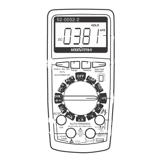
Page 2: Overview
52-0052-2 HOLD Mastercraft / /½/ AC/ DC Data Hold Range Relative Backlight Hz/% NPN PNP AUTO POWER OFF AC/DC µ A AUTO-RANGING SELECTION AUTOMATIQUE V/½/F/ CAT II F US E D 100 0V DC 400m A 750V AC µ A/mA... -
Page 3: Parts List
Before operating your multimeter, become familiar with each control. A clear understanding of how your multimeter works will help to avoid mistakes and minimize measurement errors, instrument damage and the possibility of injury. SAFETY INSTRUCTIONS This meter has been designed for safe use, depending on UL61010-1, but must be operated with caution. - Page 4 5. Common Jack Plug-in connection for black (negative) test lead. 6. V/ F / / /CAP Jack Ω Ω Ω Ω Plug-in connection for red (positive) test lead for all voltage, capacitance, frequency, resistance and continuity measurements, and diode checks. 7.
- Page 5 8. Data Hold & Backlight Button Use to hold a reading. When this button is pressed, the data being displayed will be frozen on the LCD and "HOLD" will appear. Changes in the input signals will not change the display. It can be used in all measurements modes. Press the button again to release this function and the "HOLD"...
- Page 6 Specifications: General Display: 3 3/4 digit LCD Maximum read: 4000 with automatic polarity display (no sign for positive polarity) Measuring method: A/D converter Sampling speed: 3 times/sec. Maximum common mode voltage: 500 V AC/DC Backlight for easy reading Auto shut-off switch: multimeter will be shut off after 30 minutes from last use Low battery indication: the battery symbol is displayed if battery voltage drops below operating voltage Operating environment: 5 35˚C, humidity <...
-
Page 7: Resistance (Ω)
DC CURRENT (A DC) Range Resolution Accuracy ( 1.2% rdg. + 5 dgts.) 400 µA ± 100 nA 4000 µA 1 µA 10 µA 40 mA 100 µA 400 mA 10 A 10 mA ( 2% rdg. + 5 dgts.) ±... - Page 8 DUTY-CYCLE Range Resolution Accuracy 99.9% 0.1% ( 1.2% rdg. + 2 dgts.) ± TEMPERATURE ˚C Range Resolution Accuracy 500˚C 1˚C ( 1% rdg. + 6 dgts.) ± TEMPERATURE ˚F Range Resolution Accuracy 1000˚F 1˚F ( 1% rdg. + 8 dgts.) ±...
- Page 9 Operating Instructions DC Voltage Measurement (DC V) 1. Set the function/range switch to the DC V position. 2. Insert the black (negative) test lead into the "COM" jack and the red (positive) test lead into the V/Ω/F/ / jack. NOTE: The multimeter will be in auto-ranging. 3.
- Page 10 function switch. Do not make current measurements on the 10 A scale for longer than 15 seconds every 30 minutes. Exceeding 15 seconds may cause damage to the multimeter and/or test leads.
-
Page 11: Ac Current Measurment
AC Current Measurment (AC/DC) 1. Set the function/range switch to the AC/DC position.,and Push the Select pushbutton onceor twice, until “AC” appears in LCD 2. Insert the black (negative) test lead into the "COM" jack and the red (positive) test lead into the mA/µA TEMP jack. For current measurements from 400 ma to 10 A, insert the red test lead into the 10 A jack. -
Page 12: Transistor Test/Continuity Check
Transistor Test 1. Set the function/range switch to the hFE position. 2. Determine whether the transistor is a NPN or PNP and identify the emitter, base and collector leads. Insert the leads in the proper holes in the hFE socket. 3. -
Page 13: Duty-Cycle/Temperature/Relative Value Measurements
Duty-cycle Measurement 1. Set the function/range switch to the FREQ position. 2. Insert the black (negative) test lead into the "COM" jack and the red (positive) test lead into the V/Ω /F/ / jack. NOTE: The multimeter will be in auto-ranging. 3. -
Page 14: Replacing Battery/Changing Fuses
Replacing Your Battery If the battery symbol appears on the display, the battery should be replaced. Use only fresh and correct 6F22 type 9 V battery. Turn the multimeter to the "OFF" position and disconnect the test leads. Remove the screw on the back of the multimeter, and remove the back cover.
Need help?
Do you have a question about the 52-0052-2 and is the answer not in the manual?
Questions and answers