Table of Contents
Advertisement
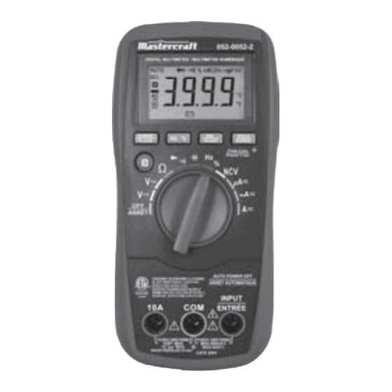
model no. 052-0052-2
Read and understand this instruction manual thoroughly
before using the product. It contains important
information for your safety as well as operating and
maintenance advice.
Keep this instruction manual for future use. Should this
product be passed on to a third party, then this
instruction manual must be included.
AUTO-RANGING
DIGITAL MULTIMETER
INSTRUCTION
MANUAL
Advertisement
Table of Contents

Related Manuals for MasterCraft 052-0052-2


Summary of Contents for MasterCraft 052-0052-2
-
Page 1: Digital Multimeter
052-0052-2 AUTO-RANGING DIGITAL MULTIMETER Read and understand this instruction manual thoroughly before using the product. It contains important information for your safety as well as operating and INSTRUCTION maintenance advice. MANUAL Keep this instruction manual for future use. Should this product be passed on to a third party, then this instruction manual must be included. -
Page 3: Safety Information
SAFETY INFORMATION This meter has been designed according to EC 61010 concerning electronic measuring instruments with a measurement category (CAT IV 600V) and pollution degree 2. WARNING To avoid possible electric shock or personal injury, follow these guidelines: Do not use the meter if it is damaged. Before you use the meter, ●... - Page 4 052-0052-2 | contact us 1-800-689-9928 When servicing the meter, use only specified replacement parts. ● Use caution when working with voltage above 30 V AC RMS, 42 ● V peak, or 60 V DC. Such voltages pose a shock hazard.
- Page 5 CAT IV - Measurement Category IV is for measurements performed ● at the source of the low-voltage installation. Examples are electricity meters and measurements on primary overcurrent protection devices and ripple control units. For measurements on main or within Measurement Category ●...
- Page 6 052-0052-2 | contact us 1-800-689-9928 CAUTION To avoid possible damage to the meter or to the equipment under test, follow these guidelines: Disconnect circuit power and discharge all capacitors thorough- ● ly before measuring resistance, diode, capacitor, temperature and continuity.
-
Page 7: Electrical Symbols
The equipment is protected throughout by double insulation or reinforced insulation. INTRODUCTION Model 052-0052-2 meter is a compact 3 3/4-digit digital multimeter for measuring DC and AC voltage, DC and AC current, resistance, continuity, diode, capacitance, frequency, duty cycle and non-contact AC voltage detection function. -
Page 8: Front Panel
052-0052-2 | contact us 1-800-689-9928 FRONT PANEL Display 3 3/4 -digit LCD, with a max. reading of 3999. "RANGE" Button Used to switch the meter between autorange mode and manual range mode as well as to select desired manual range. - Page 9 "Hz %" Button Used to switch the meter between frequency and duty cycle measurements when the rotary switch is in the "Hz/%" position. " " Button Used to switch the meter between: AC current and DC current measurement functions. ● Diode and continuity test functions.
- Page 10 052-0052-2 | contact us 1-800-689-9928 "HOLD" Button Press this "HOLD" button briefly to enter or exit Data Hold mode. Press and hold down this button for about 2 secs to turn on or off the backlight. Holster BUILT-IN BUZZER: When you press a button, the buzzer will sound a beep if this press is effective.
-
Page 11: Understanding The Display
UNDERSTANDING THE DISPLAY SYMBOL MEANING ----- Continuity test is selected. ----- Diode test is selected. ----- Autorange mode is selected. AUTO ----- Relative mode is active. ----- Data Hold mode is active. ----- Negative sign ----- AC ----- DC ----- The battery is low and must be replaced immediately. - Page 12 052-0052-2 | contact us 1-800-689-9928 Warning: To avoid false readings, which could lead to possible electric shock or personal injury, replace the battery as soon as this low battery indicator appears. Units: mV: Millivolt; V: Volt; mV, V...
-
Page 13: General Specifications
GENERAL SPECIFICATIONS Fuse Protection for "INPUT" Terminal Inputs: 400 mA/600 V FAST fuse, Min. Interrupt Rating 10000 A Fuse Protection for "10A" Terminal Inputs: 10 A/600 V FAST fuse, Min. Interrupt Rating 10000 A Display: 3 3/4-digit LCD with a max. reading of 3999 Overrange Indication: "OL"... -
Page 14: Technical Specifications
052-0052-2 | contact us 1-800-689-9928 TECHNICAL SPECIFICATIONS Readings are accurate for a period of 1 year after calibration at 64 to 82ºF (18 to 28ºC), with relative humidity up to 75%. Accuracy specifications take the form of: ± [(% of Reading) + (Number of Least Significant Digits)]... - Page 15 AC VOLTAGE Overrange Range Resolution Accuracy Indication 1 mV ± (0.8% + 5) “OL” shown on 40 V 10 mV the display ± (1.2% + 5) 400 V 0.1 V 600 V See[1] Input Impedance: 10 MΩ Frequency Range: 40 – 400 Hz Response: Average, calibrated in RMS of sine wave Max.
- Page 16 052-0052-2 | contact us 1-800-689-9928 Overload Protection: 400 mA/600 V FAST fuse (for protection for "INPUT" terminal inputs) 10 A/600 V FAST fuse (for protection for "10A" terminal inputs) Max. Allowable Input Current: 10 A (For inputs > 2 A: duration < 10 secs, interval >15 minutes) NOTE: The 10 A range is accurate from 20 to 100% of range.
- Page 17 RESISTANCE Overrange Range Resolution Accuracy Indication 400 Ω 0.1 Ω 4 kΩ 1 Ω ± (1.0% + 5) “OL” shown on 40 kΩ 10 Ω the display 400 kΩ 100 Ω 4 MΩ 1 kΩ ± (1.5% + 5) 40 MΩ 10 kΩ...
-
Page 18: Duty Cycle
052-0052-2 | contact us 1-800-689-9928 DUTY CYCLE Range Resolution Accuracy Remark 5 – 95% 0.1% ± ( 2.0% + 7 ) Auto-range Input Voltage: 4 – 10 V P-P Frequency Range: 4 Hz – 1 kHz CAPACITANCE Range... -
Page 19: Operating Instructions
DIODE Range Description Remark The display shows the Open Circuit Voltage: approx. forward voltage about 3 V drop of the diode. Test Current: about 0.8 mA CONTINUITY Range Description The built-in buzzer will sound if the resistance is less than about 20 Ω. The buzzer may or may not sound if the resistance is between 20 and 150 Ω. -
Page 20: Data Hold Mode
052-0052-2 | contact us 1-800-689-9928 When you perform a new measurement, the display shows the difference between the reference and the new measurement. To exit Relative mode, just press the "REL" button again. The symbol "REL" disappears. NOTE: When in Relative mode, the actual value of the object under test must not exceed the full-scale value of the selected range. -
Page 21: Measuring Dc Voltage
MEASURING DC VOLTAGE Connect the black test lead to the "COM" terminal and the red test lead to the "INPUT" terminal. Set the function switch to the V position. Connect the test leads across the source or circuit to be tested. Read the reading on the display. -
Page 22: Measuring Ac Voltage
052-0052-2 | contact us 1-800-689-9928 MEASURING AC VOLTAGE Connect the black test lead to the "COM" terminal and the red test lead to the "INPUT" terminal. Set the function switch to the V position. Connect the test leads across the source or circuit to be tested. -
Page 23: Measuring Dc Or Ac Current
MEASURING DC OR AC CURRENT Connect the black test lead to the "COM" terminal. If the current to be measured is less than 400 mA, connect the red test lead to the "INPUT" terminal. If the current is between 400 mA and 10 A, connect the red test lead to the "10A"... - Page 24 052-0052-2 | contact us 1-800-689-9928 Break the circuit path to be tested, and connect the test leads in series with the circuit. Turn on power to the circuit, then read the display. For DC current measurements, the polarity of the red test lead connec- tion will be indicated as well.
-
Page 25: Measuring Resistance
MEASURING RESISTANCE Connect the black test lead to the "COM" terminal and the red test lead to the "INPUT" terminal. Set the function switch to Ω position. Connect the test leads across the object to be tested. Read the reading on the display. NOTE: For measurements >... -
Page 26: Continuity Test
052-0052-2 | contact us 1-800-689-9928 CONTINUITY TEST Connect the black test lead to the "COM" terminal and the red test lead to the "INPUT" terminal. Set the function switch to / position. Press the button until the display shows " ". -
Page 27: Diode Test
DIODE TEST Connect the black test lead to the "COM" terminal and the red test lead to the "INPUT" terminal. (Note: The polarity of the red lead is positive " + " .) Set the function switch to / position. Press the button until the display shows "... -
Page 28: Measuring Frequency
052-0052-2 | contact us 1-800-689-9928 MEASURING FREQUENCY Connect the black test lead to the "COM" terminal and the red test lead to the "INPUT" terminal. Set the function switch to Hz/% position. Then press the "Hz %" button until the display shows "Hz". -
Page 29: Measuring Duty Cycle
MEASURING DUTY CYCLE Connect the black test lead to the "COM" terminal and the red test lead to the "INPUT" terminal. Set the function switch to Hz/% position. Press the "Hz %" button until the display shows "%". Connect the test leads to the circuit to be tested. The reading on the display is the duty cycle value of the square wave being measured. -
Page 30: Measuring Capacitance
052-0052-2 | contact us 1-800-689-9928 MEASURING CAPACITANCE Adaptor Set the function switch to position. Connect the adaptor to the "COM" and "INPUT" terminals, as indicated in the figure. If the display does not read zero, press the REL button to zero the display;... -
Page 31: Non-Contact Ac Voltage Detection
NON-CONTACT AC VOLTAGE DETECTION Make sure that the meter has been turned on, then set the function switch to NCV position. Move the top of the meter close to the object to be tested. When the meter detects AC voltage, the built-in buzzer will sound. -
Page 32: Automatic Power Off
052-0052-2 | contact us 1-800-689-9928 WARNING When you just set the function switch to NCV position, the built-in buzzer may sound several beeps. This is normal and does not affect subsequent detections. Because of the meter's detection limit, a line (or conductor) under test may be live even if the built-in buzzer does not sound. -
Page 33: General Maintenance
MAINTENANCE Except replacing fuse and battery, never attempt to repair or service the meter unless you are qualified to do so and have the relevant calibration, performance test, and service instructions. Store the meter in a dry place when not in use. Don't store it in an intense electromagnetic field environment. -
Page 34: Battery And Fuse Replacement
052-0052-2 | contact us 1-800-689-9928 BATTERY AND FUSE REPLACEMENT Warning: To avoid false readings, which could lead to possible electric shock or personal injury, replace the battery as soon as the low battery indicator ( ) appears. To prevent damage or injury, install only replacement fuses with the specified amperage, voltage, and interrupt ratings. -
Page 35: Warranty
The contents of this manual can not be used as the reason to use the meter for any special application. WARRANTY This Mastercraft product carries a one-year warranty against defects in workmanship and materials. This product is not guaranteed against wear, breakage or misuse.
Need help?
Do you have a question about the 052-0052-2 and is the answer not in the manual?
Questions and answers