Table of Contents
Advertisement
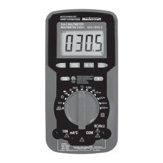
model no. 052-1899-2
Read and understand this instruction manual thoroughly
before using the product. It contains important
information for your safety as well as operating and
maintenance advice.
Keep this instruction manual for future use. Should this
product be passed on to a third party, then this
instruction manual must be included.
MULTIMETER
INSTRUCTION
MANUAL
Advertisement
Table of Contents

Related Manuals for MasterCraft 052-1899-2


Summary of Contents for MasterCraft 052-1899-2
- Page 1 052-1899-2 MULTIMETER Read and understand this instruction manual thoroughly before using the product. It contains important INSTRUCTION information for your safety as well as operating and maintenance advice. MANUAL Keep this instruction manual for future use. Should this product be passed on to a third party, then this instruction manual must be included.
-
Page 3: General Description
GENERAL DESCRIPTION This multimeter is 4000 count, 3 3/4-digit digital multimeter. It can be used to measure DC and AC voltage, DC and AC current, resistance, capacitance, frequency, diode, temperature, continuity, duty cycle, sound level, relative humidity and illumination. It can be used as a test tool for environment and devices and is a high-perfor- mance and versatile multimeter. - Page 4 052-1899-2 | contact us 1-800-689-9928 Do not use the meter if it operates abnormally. Protection may ● be impaired. When in doubt, have the meter serviced. Do not operate the meter around explosive gas, vapour, or dust. ●...
- Page 5 Do not use the meter in a manner not specified by this manual ● or the safety features of the meter may be impaired. Remaining endangerment: ● When an input terminal is connected to dangerous live potential it is to be noted that this potential at all other terminals can occur! CAT III ●...
- Page 6 052-1899-2 | contact us 1-800-689-9928 CAUTION To avoid possible damage to the meter or to the equipment under test, follow these guidelines: Disconnect circuit power and discharge all capacitors before ● testing resistance, diode, capacitor, temperature and continuity.
-
Page 7: Electrical Symbols
ELECTRICAL SYMBOLS Alternating current Direct current Both direct and alternating current Caution, risk of danger. Refer to the operating manual before use. Caution, risk of electric shock. Earth (ground) terminal Fuse Conforms to European Union directives The equipment is protected throughout by double insulation or reinforced insulation. - Page 8 052-1899-2 | contact us 1-800-689-9928 DESCRIPTION Figure 1 Display 3 3/4-digit LCD, with a max. reading of 3999. "RANGE" Button Used to switch the meter between the autorange mode and the manual range mode.
- Page 9 3. "FUNC" Button Used to switch the meter between DC and AC functions, or between diode and continuity functions. 4. "HOLD" Button Used to hold the present reading on the display. 5. Function / Range Switch Used to select the desired function and range as well as to turn on or off the meter.
- Page 10 052-1899-2 | contact us 1-800-689-9928 11. "REL" Button It can be used to set the meter to Relative Mode. 12. "Hz%" Button It can be used to switch the meter between frequency and duty cycle measurements. 13. Holster SENSOR INSTRUCTION The sensors are located at the top of the meter and inside the case.
-
Page 11: Lcd Display
LCD DISPLAY Figure 3 Continuity test is selected Diode test is selected Autorange mode is selected Relative mode is active Data Hold is enabled Negative sign Battery is low and should be replaced... - Page 12 052-1899-2 | contact us 1-800-689-9928 10. Units on the LCD mV, V Voltage unit. mV: Millivolt; V: Volt; 1 V=10 μA, mA, Current unit μΑ: Microamp; mA: Milliamp; A: Ampere; 1Α=10 mA=10 μΑ Ω, kΩ, Resistance unit MΩ...
-
Page 13: General Specifications
GENERAL SPECIFICATIONS Display: 3 3/4-digit LCD, with a max. reading of 3999 Overrange Indication: "OL" shown on the LCD Negative Polarity Indication: " - " displayed automatically Sampling Rate: 2 – 3 times/sec Operating Temperature: 32 to 104ºF (0 to 40ºC), <75% RH Storage Temperature: -34 to 140ºF (-30 to 60ºC), <85% RH Operating Altitude: 0–6560' (0–2000 m) Battery: 9 V, 6F22 or equivalent... - Page 14 052-1899-2 | contact us 1-800-689-9928 DC VOLTAGE RANGE RESOLUTION ACCURACY ±(1.0% + 5) 400 mV 0.1 mV 1 mV 40 V 10 mV ±(0.8% + 3) 300 V 100 mV Input Impedance: 400 mV range: > 1000 MΩ...
- Page 15 DC CURRENT RANGE RESOLUTION ACCURACY 400 μΑ 0.1 μΑ 4000 μΑ 1 μΑ 40 mA 10 μΑ ±(1.2% + 3) 400 mA 100 μΑ 1 mA ±(1.8% + 3) 10 A 10 mA ±(2.0% + 5) Overload Protection: For "mA°C" jack inputs: Fuse, 500 mA/300 V, fast action For "10A"...
- Page 16 052-1899-2 | contact us 1-800-689-9928 Overload Protection: For "mA°C" jack inputs: Fuse, 500 mA/300 V, fast action For "10 A" jack inputs: Fuse, 10 A/300 V, fast action Max. Input Current: 10 A (For inputs > 5 A: measurement duration<10 secs, interval >15 minutes)
- Page 17 FREQUENCY RANGE RESOLUTION ACCURACY 10 Hz 0.01 Hz ± (1.0% + 3) 100 Hz 0.1 Hz 1 kHz 1 Hz ± (0.8% + 3) 10 kHz 10 Hz 100 kHz 100 Hz ± (1.0% + 3) 200 kHz 1 kHz >200 kHz not specified Input voltage: 1 –...
-
Page 18: Duty Cycle
052-1899-2 | contact us 1-800-689-9928 TEMPERATURE RANGE RESOLUTION ACCURACY -20 to 400ºC 0.1ºC ±1.5%±3ºC 400 to 1000ºC 1ºC ±2%±3ºC Overload Protection: Fuse, 500 mA/300 V, fast action. NOTE: Use a K type thermocouple. Accuracy does not include error of the thermocouple probe. - Page 19 HUMIDITY (%RH) RANGE RESOLUTION ACCURACY 30 – 90% 0.1% --------------- Working Temperature: 32 to 104ºF (0 to 40ºC) Response Time: 45% RH 90% RH ≤ 10 minutes 90% RH 45% RH ≤ 15 minutes SOUND LEVEL (dB) RANGE RESOLUTION ACCURACY 35 –...
-
Page 20: Operating Instructions
052-1899-2 | contact us 1-800-689-9928 DIODE AND CONTINUITY RANGE INTRODUCTION TEST CONDITION The approx. forward Open Circuit Voltage: voltage drop of the about 1.5 V diode will be displayed. Overload Protection: 300 V DC/AC The built-in buzzer will... -
Page 21: Data Hold Mode
Press "REL" button. The meter enters Relative mode and stores the present reading as a reference for subsequent measure- ments. "REL" appears on the display as an indicator. The display reads zero. The display shows the difference between the reference and a new measurement. - Page 22 052-1899-2 | contact us 1-800-689-9928 To exit manual range mode, press and hold down the "RANGE" button for about 2 seconds. The meter returns to autorange mode. Built- in Buzzer When you press a button, the built-in buzzer will give a beep if the press is effective.
-
Page 23: Measuring Dc Or Ac Current
Measuring DC or AC Voltage Connect the black test lead to the "COM" jack and the red test lead to the "VΩHz " jack. Set the range switch to the "V " range. Press "FUNC" button to select DC or AC voltage measurement. If you use manual range mode and the magnitude of the voltage to be measured is not known beforehand, select the highest range and then reduce it range by range until satisfactory... - Page 24 052-1899-2 | contact us 1-800-689-9928 Press "FUNC" button to select DC or AC current measurement. Connect the black test lead to the "COM" jack. If the current to be measured is less than 400 mA, connect the red test lead to the "mA°C"...
-
Page 25: Measuring Resistance
Measuring Resistance Connect the black test lead to the "COM" jack and the red test lead to the "VΩHz " jack (Note: The polarity of the red lead is positive " + " ). Set the range switch to Ω range. Connect test leads across the load to be measured. -
Page 26: Continuity Test
052-1899-2 | contact us 1-800-689-9928 Continuity Test Connect the black test lead to the "COM" jack and the red test lead to the "VΩHz " jack ( Note: The polarity of the red lead is positive " + " ). - Page 27 NOTE: Before measurement, make sure that the capacitor to be measured has been discharged. For a high capacitance measurement, it may take about 30 seconds for the meter to measure capacitance. To improve the accuracy of low-capacitance measure- ments, subtract the residual capacitance of the meter and the test leads.
-
Page 28: Diode Test
052-1899-2 | contact us 1-800-689-9928 Diode Test Connect the black test lead to the "COM" jack and the red test lead to the "VΩHz " jack ( Note: The polarity of the red lead is positive " + " ). -
Page 29: Measuring Relative Humidity
Set the range switch to "°C" position. Connect the negative " - " (or black) plug of the Κ type thermocouple to the "COM" jack, and the positive " + " (or red ) plug to the "mA°C" jack. Connect the other end of the thermocouple to the object to be measured. - Page 30 052-1899-2 | contact us 1-800-689-9928 Measuring Sound Level Figure 4 You can use the meter to measure sound level with the built-in sound sensor. The sensor is located near the mark "dB" on the top of the meter (Figure 2).
- Page 31 Measuring Intensity of Illumination Figure 5 You can use the meter to measure illuminance with the built-in light sensor. The sensor is located near the mark "Lux" on the top of the meter (Figure 2). Set the range switch to "×Lux" position. Point the light sensor to the light source to be measured in order that the light can reach the sensor through the small white cover of the sensor (Figure 5).
-
Page 32: Auto Power Off
052-1899-2 | contact us 1-800-689-9928 Figure 6 λ - Wavelength (nm) Relative Spectral Sensitivity vs. λ - Wavelength Auto Power Off The display blanks and the meter goes into a "Sleep" mode if you have not changed the rotary switch position or pressed a button for about 15 minutes. -
Page 33: General Maintenance
MAINTENANCE Warning Except replacing batteries and fuses, do not attempt to repair or service the meter unless you are qualified to do so and have the relevant calibration, performance test, and service instructions. The meter should be stored only in dry place. General Maintenance Periodically wipe the case with a damp cloth and mild detergent. -
Page 34: Replacing The Battery And Fuse
052-1899-2 | contact us 1-800-689-9928 Replacing the Battery and Fuse Warning To avoid false readings, which could lead to possible electric shock or personal injury, replace the battery as soon as the battery indicator (" ") appears. To prevent damage or injury, install only replacement fuse of the same ratings. - Page 35 The contents of this manual can not be used as the reason to use the meter for any special application. WARRANTY This Mastercraft product carries a one-year warranty against defects in workmanship and materials. This product is not guaranteed against wear, breakage or misuse.
Need help?
Do you have a question about the 052-1899-2 and is the answer not in the manual?
Questions and answers