
Related Manuals for Alpha-InnoTec LW 101


Summary of Contents for Alpha-InnoTec LW 101
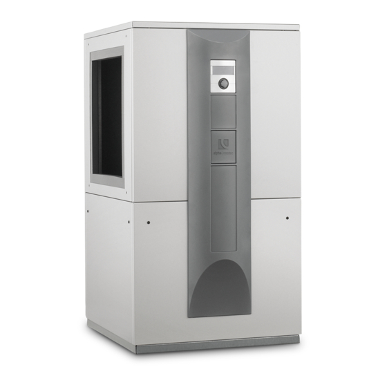
- Page 1 Operati ng manual aIr/water Heat PumPs Inside installation Lw 101 Lw 121 Lw 150H(L) We reserve the right to modify technical specifications without prior notice. UK830533/200610 © Alpha-InnoTec GmbH...
-
Page 2: Please Read First
Please read first symbols This operating manual provides important information The following symbols are used in the operating manual. on the handling of the unit. It is an integral part of the They have the following meaning: product and must be stored so that it is accessible in the immediate vicinity of the unit. -
Page 3: Table Of Contents
150H(l) .................30 cUSTomeR SeRvIce ..............5 dImeNSIoNAl dRAWINGS ANd INSTAllATIoN plANS WARRANTy / GUARANTee ..........5 Dimensional drawings LW 101 • LW 150H .....31 dimensional drawings lW 150Hl ........32 dISpoSAl ..................5 Installation plans LW 101 • LW 150H(L) Installation plan version 1 ..........33 INfoRmATIoN foR opeRAToRS Installation plan version 2 ..........34... -
Page 4: Intended Use
Intended use safety The unit may be used only for the intended purpose. The unit is operationally safe when used for the intended This means: purpose. The construction and design of the unit conform to the state of the art, all relevant dIN/vde •... -
Page 5: Customer Service
Customer service CautIon. For safety reasons: never disconnect the unit from the power for technical assistance, please contact your qualified supply, unless the unit is being opened. technician or the manufacturer's local service partner. overview "customer service". CautIon. Install the heat pump only indoors and operate only with outside air as the heat source. -
Page 6: Functioning Principle Of Heat Pump System
Functioning principle of heat Heat quantity recording pump system In addition to proof of the unit's efficiency, heating legislation also requires heat quantity recording (referred Heat pumps operate on the principle of a refrigerator: to as Wme in this manual). The Wme is mandatory with the same technology, only with the opposite effect. -
Page 7: Care Of The Unit
Care of the unit Cleaning and flushing of unit Components The outer surfaces of the unit can be cleaned with a CautIon! damp cloth and household cleaning products. unit components cleaned and flushed only by customer service do not use cleaning or care products that contain personnel authorised by the manufacturer. -
Page 8: Scope Of Delivery
scope of delivery proceed as follows: example of scope of delivery: Inspect delivery for outwardly visible signs of damage. view 1: check to make sure that delivery is complete. Any defects or incorrect deliveries must be claimed immediately. notICe. note the model. Check the air blow-out direction of the unit. -
Page 9: Installation And Assembly
Installation and assembly transport to installation loCation To prevent damage during transport, always transport observe the following when performing all work: the unit to final installation location in its original packag- ing, using a lifting truck. notICe. If it is not possible to transport the unit to the final instal- always comply with applicable accident lation location using a lifting truck, you can also transport prevention regulations, statutory regula-... - Page 10 lifting the unit with pipes on the back of the unit, remove the sealing grommet… The units can be lifted with " and/or 1" pipes (provided by customer) that are suitable for the weight of the respective unit. Special holes are provided in the frame for this purpose.
-
Page 11: Installation
installation put the unit in its final installation location. make sure that the frame of the unit is in full contact with Set the unit on a stable, solid and level, preferably the underlying surface… sound-insulated surface. make sure that the foundation is designed for the weight of the heat pump. -
Page 12: Mounting The Air Ducts
mounting the air duCts Affix an additional part as illustrated… notICe. note the air blow-out direction of the unit. – units with the abbreviation L in the model designation blow the air out to the left (when viewed from the control side). - Page 13 air duCts assembly Install the wall duct in the masonry from the house exterior. This can either be done during proceed as follows: the construction phase (by means of sealing)… Remove the parts necessary for the assembly of the air duct(s) from their respective boxes… notICe.
- Page 14 notICe. notICe. after the other end of the air duct has Don't forget: been secured to the heat pump, close the after the air ducts have been secured to opening between the wall duct and the air the heat pump, close the opening between duct using the bentonite waterstop tape the wall duct and the air duct using the included with delivery.
- Page 15 wire mesh grille and weather / rain guards assembly proceed as follows: Remove the wire mesh grille and the weather / rain guards as well as the assembly frame and fastening material from their respective boxes… notICe. If the wall duct is positioned above ground level, attach the weather guard.
-
Page 16: Installation / Connection To Heating Circuit
installation / ConneCtion to heating CirCuit proceed as follows: Rinse heating circuit thoroughly prior to connecting Danger! the unit to the heating circuit… Danger of fatal injury due to electric shock! notICe. Before opening the unit, disconnect the Contamination and deposits in the heating system from the power supply and secure circuit can cause malfunctions. -
Page 17: Condensate Discharge
Pressure relief Condensate disCharge The condensation water that accumulated from the air equip the heating circuit in accordance with local stand- must be drained via the pre-mounted hose in the unit ards and directives with a safety valve and an expansion for condensate discharge. -
Page 18: Circulating Pumps
Circulating pumps electrical connections observe the following when performing all work: CautIon. always note the model. Danger! Danger of fatal injury due to electric Do not use regulated circulating pumps. shock! Circulating pumps and domestic hot water electrical connections may be installed circulation pumps must be multi-stage only by qualified electricians. - Page 19 lead 230 v power cable, power cable for circulat- notICe. ing pumps and cable for external temperature sen- Factory setting for the electric heating sor through the rubber sockets on the facing panel element in units with integrated electic in the unit… heating elements is 6 kW (9 kW).
-
Page 20: Flushing, Filling And Bleeding The System
Flushing, filling and bleeding the system proceed as follows: flush, fill and bleed the heating circuit… In addition, bleed the condenser of the heat pump… • open the lower facing panel… • open the bleed valve… following bleeding, close the lower facing panel. Insulating the hydraulic connections Insulate the vibration decouplers and the pipes of the... -
Page 21: Installation Of The Control Element
Installation of the control proceed as follows: element Hang the control element's hooks on the recesses of the front facade (either in the upper or lower recesses)… Danger! Danger of fatal injury due to electric shock! electrical connections may be installed only by qualified electricians. - Page 22 notICe. a connection to a computer or a network can be installed via the left bushing on the bottom of the control element, allowing the heating and heat pump regulator to be controlled remotely. one pre-condition is that a screened network cable (category 6) be installed through the unit when installing the unit.
-
Page 23: Installation And Removal Of The Screen
Installation and removal of the beginning first on one side and moving upwards, screen lock the screen's snap-in lugs in place in the slots provided on the front of the facade… installing the sCreen notICe. the screen is provided at the time of delivery so that the control element may be inserted in the upper recesses of the front facade. -
Page 24: Commissioning
Commissioning The heat pump system will be commissioned by cus- tomer service personnel authorised by the manu- facturer. A charge is made for commissioning! Danger! the unit may be commissioned only with safety temperature limiter the air ducts and weather grille or rain guard installed and with the covers closed. -
Page 25: Dismantling
Dismantling Danger! Danger of fatal injury due to electric shock! electrical connections may be installed only by qualified electricians. Before opening the unit, disconnect the system from the power supply and secure it from being switched back on! Danger! only qualified heating or cooling system technicians are allowed to remove the unit from the system. -
Page 26: Technical Data / Scope Of Delivery
technical data / scope of delivery Model designation Heat pump type Brine/water ı Air/water ı Water/water • applicable ı — not applicable Installation location Indoors ı Outdoors • applicable ı — not applicable Conformity Performance data Heating capacity/COP at 2 Compressors kW ı... - Page 27 LW 101 LW 121 LW 150H (L) — ı • ı — — ı • ı — — ı • ı — • ı — • ı — • ı — • • • — — — 10,3 ı 4,2 12,8 ı...
-
Page 28: Performance Curves
Compressor(s) Leistungs-Druckverlustkurven Bezeichnung: Änd./Ä.M./Ersteller/Datum LW 101 (A) Seite: 1/1 - / PEP026-2009 / Opel / 16.04.10 Zeichnungsnummer: 823152 Datei: 823152 Leistungs- Druckverlustkurven LW 101 (A).xls We reserve the right to modify technical specifications without prior notice. UK830533/200610 © Alpha-InnoTec GmbH... - Page 29 Performance curves Lw 121 Qh (kW) Temp„ (°C) Pe (kW) 35°C 1VD 50°C 1VD Temp„ (°C) Temp„ (°C) ∆p (bar) ∆p” “” (m³/h) 823153 Legende: DE823129L/170408 “” Volumenstrom Heizwasser Temp„ Temperatur Wärmequelle Heizleistung Legend: UK823129L/170408 Leistungsaufnahme “” Volume flow, heating water Coefficient of performance / Leistungszahl ∆p”...
-
Page 30: Heating Capacity/Cop / Power Consumption
Lw 150H(L) Performance curves Qh (kW) Temp„ (°C) Pe (kW) 35°C 1VD 50°C 1VD 65°C 1VD Temp„ (°C) Temp„ (°C) ∆p (bar) ∆p” “” (m³/h) 823125 Legende: DE823129L/170408 “” Volumenstrom Heizwasser Temp„ Temperatur Wärmequelle Heizleistung Leistungsaufnahme Legend: UK823129L/170408 Coefficient of performance / Leistungszahl “”... -
Page 31: Dimensional Drawings Lw 101 • Lw 150H
Dimensional drawings LW 101 • LW 150H 4x M8 1353 1298 1261 4x M8 1298 1261 Legende: D819352- Legend: UK819352 Technische Änderungen vorbehalten. All dimensions in mm. Alle Maße in mm. Front view Vorderansicht Side view from left Seitenasicht von links... -
Page 32: Dimensional Drawings Lw 150Hl
Lw 150HL Dimensional drawings 1353 1298 1261 4x M8 4x M8 1298 1261 Legende: D819170a Legend: UK819170a Pos. Bezeichnung Technische Änderungen vorbehalten. All dimensions in mm. Alle Maße in mm. Bedienteil Front view Heizwasser Austritt (Vorlauf) G 1" DIN ISO 228 Vorderansicht Side view from left Seitenasicht von links... -
Page 33: Installation Plan Version 1
Lw 101 • Lw 150H(L) Installation plan Version 1 ≥700 ≥700 ≥ 2535 Pos. Bezeichnung ß Legend: UK819345-1 All dimensions in mm. Bei Fertigwandstärke 240 bis 320 2060 Zubehör: Wanddurchführung 800x800x420 Item Designation Dim. Bei Fertigwandstärke 320 bis 400 1980 Zubehör: Luftkanal 700x700x450... -
Page 34: Installation Plan Version 2
Lw 101 • Lw 150H(L) Installation plan Version 2 ≥700 ≥700 ≥2535 ß Pos. Bezeichnung Legend: UK819345-2 All dimensions in mm. Zubehör: Wanddurchführung 800x800x420 Bei Fertigwandstärke 240 bis 320 2060 Item Designation Dim. Zubehör: Luftkanal 700x700x450 Bei Fertigwandstärke 320 bis 400... -
Page 35: Installation Plan Version 3
Lw 101 • Lw 150H(L) Installation plan Version 3 1570 ≥700 ≥700 ≥2670 ß Pos. Bezeichnung Bei Fertigwandstärke 240 bis 320 Zubehör: Wanddurchführung 800x800x420 Legend: UK819345-3 All dimensions in mm. Bei Fertigwandstärke 320 bis 400 Zubehör: Luftkanal 700x700x450 Zubehör: Luftkanalbogen 700x700x750... -
Page 36: Installation Plan Version 4
Lw 101 • Lw 150H Installation plan Version 4 2570 ≥700 ≥700 ≥3670 Legend: UK819345-4 All dimensions in mm. ß Pos. Bezeichnung Bei Fertigwandstärke 240 bis 320 Item Designation Dim. Zubehör: Wanddurchführung 800x800x420 Bei Fertigwandstärke 320 bis 400 With finished wall thickness 240 to 320 Zubehör: Luftkanal 700x700x450... -
Page 37: Installation Plan Version 5
Installation plan Version 5 Lw 150HL 2570 ≥700 ≥700 ≥3670 ß Pos. Bezeichnung Bei Fertigwandstärke 240 bis 320 Zubehör: Wanddurchführung 800x800x420 Legend: UK819345-5 All dimensions in mm. Bei Fertigwandstärke 320 bis 400 Zubehör: Luftkanal 700x700x450 Item Designation Dim. Zubehör: Luftkanal 700x700x1000 Legende: 819345 With finished wall thickness 240 to 320... -
Page 38: Dimensional Drawings Lw 121
Lw 121 Dimensional drawings 4x M8 1523 1381 1372 4x M8 1381 1372 Legende: Legend: D819354- UK819354 Technische Änderungen vorbehalten. All dimensions in mm. Alle Maße in mm. Front view Vorderansicht Side view from left Seitenasicht von links Side view from right Seitenansicht von rechts Rückansicht Rear view... -
Page 39: Installation Plan Version 1
Installation plan Version 1 Lw 121 ≥700 ≥700 ≥ 2630 Pos. Bezeichnung Maß Pos. Bezeichnung Bei Fertigwandstärke 240 bis 320 2160 Zubehör: Wanddurchführung 800x800x420 Bei Fertigwandstärke 320 bis 400 2080 Zubehör: Luftkanal 700x700x450 Bei Fertigwandstärke 240 bis 320 Zubehör: Luftkanal 700x700x1000 Legend: UK819346-1 All dimensions in mm. -
Page 40: Installation Plan Version 2
Lw 121 Installation plan Version 2 ≥700 ≥700 ≥2630 Pos. Bezeichnung Maß Pos. Bezeichnung Bei Fertigwandstärke 240 bis 320 2160 Legend: UK819346-2 All dimensions in mm. Zubehör: Wanddurchführung 800x800x420 Bei Fertigwandstärke 320 bis 400 2080 Item Designation Dim. Zubehör: Luftkanal 700x700x450 Bei Fertigwandstärke 240 bis 320 With finished wall thickness 240 to 320 2160... -
Page 41: Installation Plan Version 3
Installation plan Version 3 Lw 121 1665 ≥700 ≥700 ≥2770 Pos. Bezeichnung Pos. Bezeichnung Maß Legend: UK819346-3 All dimensions in mm. Zubehör: Wanddurchführung 800x800x420 Bei Fertigwandstärke 240 bis 320 Item Designation Dim. Zubehör: Luftkanal 700x700x450 Bei Fertigwandstärke 320 bis 400 Zubehör: Luftkanalbogen 700x700x750 With finished wall thickness 240 to 320 Legende:... -
Page 42: Installation Plan Version 4
Lw 121 Installation plan Version 4 2665 ≥700 ≥700 ≥3770 Legend: UK819346-4 All dimensions in mm. Pos. Bezeichnung Pos. Bezeichnung Maß Item Designation Dim. Zubehör: Wanddurchführung 800x800x420 Bei Fertigwandstärke 240 bis 320 With finished wall thickness 240 to 320 Zubehör: Luftkanal 700x700x450 Bei Fertigwandstärke 320 bis 400 With finished wall thickness 320 to 400 Zubehör: Luftkanal 700x700x1000... -
Page 43: Terminal Diagrams
Lw 101 – Lw 121 3~N/PE/400V/50Hz 3~N/PE/400V/50Hz 3~N/PE/400V/50Hz 1~N/PE/230V/50Hz B10 A ZW2/SST We reserve the right to modify technical specifications without prior notice. UK830533/200610 © Alpha-InnoTec GmbH... -
Page 44: Lw 150H(L)
Lw 150H(L) terminal diagram 3~N/PE/400V/50Hz 3~PE/400V/50Hz 3~N/PE/400V/50Hz 1~N/PE/230V/50Hz B10 A ZW2/SST We reserve the right to modify technical specifications without prior notice. UK830533/200610 © Alpha-InnoTec GmbH... -
Page 45: Circuit Diagrams
Circuit diagram 1/3 Lw 101 – Lw 121 +10V 0-10V We reserve the right to modify technical specifications without prior notice. UK830533/200610 © Alpha-InnoTec GmbH... - Page 46 Lw 101 – Lw 121 Circuit diagram 2/3 We reserve the right to modify technical specifications without prior notice. UK830533/200610 © Alpha-InnoTec GmbH...
- Page 47 Circuit diagram 3/3 Lw 101 – Lw 121 We reserve the right to modify technical specifications without prior notice. UK830533/200610 © Alpha-InnoTec GmbH...
-
Page 48: Lw 150H(L)
Lw 150H(L) Circuit diagram 1/3 We reserve the right to modify technical specifications without prior notice. UK830533/200610 © Alpha-InnoTec GmbH... - Page 49 Circuit diagram 2/3 Lw 150H(L) ZUP/ZIP We reserve the right to modify technical specifications without prior notice. UK830533/200610 © Alpha-InnoTec GmbH...
- Page 50 Lw 150H(L) Circuit diagram 3/3 We reserve the right to modify technical specifications without prior notice. UK830533/200610 © Alpha-InnoTec GmbH...
- Page 51 We reserve the right to modify technical specifications without prior notice. UK830533/200610 © Alpha-InnoTec GmbH...
-
Page 52: Ec Declarations Of Conformity
eC declaration of conformity The undersigned confirms that the following designated device(s) as designed and marketed by us fulfill the standardized ec directives, the ec safety standards and the product-specific ec standards. In the event of modification of the device(s) without our approval, this declaration shall become invalid. designation of the deviCe(s) Heat pump unit model... - Page 53 In the event of modification of the device(s) without our approval, this declaration shall become invalid. designation of the deviCe(s) Heat pump unit model number unit model number LW 71A 100 540 LW 101 100 530 LW 81A 100 541 LW 121 100 531 LW 101A 100 542 LW 140...
-
Page 55: General Checklist
General checklist for preparation of the Completion report for heat pump systems The general checklist is intended as an aid for the installation and assembly personnel. It makes no claim to be exhaustive. Nevertheless, all items must be checked carefully for compliance. Heat source air Heating ... -
Page 57: Completion Report For Heat Pump Systems
Completion report for heat pump systems in de: Alpha-InnoTec customer service department 01803 003550 (0,09 €/min. aus dt. festnetz, mobilfunkpreise können abweichen) in AT: Alpha-InnoTec customer service department 0820 500644 (0,15 €/min. aus dem festnetz und mobilfunk) Completion report and reQuest for faCtory Commissioning during factory commissioning, the system will be inspected to ensure that it is functioning properly. -
Page 58: Customer Service
Customer service addresses in the event of a serviCe Call for a current list and additional partners of the manufacturer, please visit www.alpha.innotec.com. Alpha-InnoTec GmbH Industriestrasse 3 95359 Kasendorf Tel.: +49 (0) 1803 003530 * Suisse romande fax: +49 (0) 1803 003550 * Alpha-InnoTec Schweiz AG info@alpha-innotec.com ch. - Page 59 Alpha-InnoTec france eURl NATHAN Import/export b.v. parc d‘activités economiques "les couturiers" Impact 73 16, rue des couturières 6921 RZ duiven 67240 bischwiller Tel.: +31 (0) 26 445 98 45 Tel.: +33 (0) 3 880 624 10 fax: +31 (0) 26 445 93 73 fax: +33 (0) 3 880 624 11 info@nathan.nl info@alpha-innotec.fr...
Need help?
Do you have a question about the LW 101 and is the answer not in the manual?
Questions and answers