
Subscribe to Our Youtube Channel
Related Manuals for Alpha-InnoTec LW 140


Summary of Contents for Alpha-InnoTec LW 140
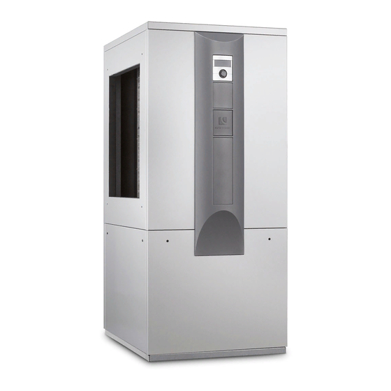
- Page 1 Operati ng manual aIr/water Heat PumPs Inside installation Lw 140(L) –Lw 310(L) Lw 320H(L) We reserve the right to modify technical specifications without prior notice. UK830534/200610 © Alpha-InnoTec GmbH...
-
Page 2: Please Read First
Please read first symbols This operating manual provides important information The following symbols are used in the operating manual. on the handling of the unit. It is an integral part of the They have the following meaning: product and must be stored so that it is accessible in the immediate vicinity of the unit. -
Page 3: Table Of Contents
INfoRmATIoN foR opeRAToRS dimensional drawings LW 140L – LW 180L • LW 320HL ......36 opeRATING pRINcIpleof HeAT pUmpS......6 Installation plans LW 140(L) – LW 180(L) • LW 320H(L) AReA of UTIlISATIoN ............6 Installation plan version 1 ..........37 HeAT qUANTITy RecoRdING ..........6 Installation plan version 2 ..........38... -
Page 4: Intended Use
Intended use safety and security The unit may be used only for the intended purpose. The unit is operationally safe when used for the intend- That means: ed purpose. The construction and design of the unit con- form to the state of the art, all relevant dIN/vde regu- •... -
Page 5: Customer Services
Customer services WarnIng! unit contains refrigerants! Leaking refrigerant could result in person- for technical information please contact a qualified tech- al injury or material damage. therefore: nician or the manufacturer's local partner. – shut down unit. – notify the manufacturer’s authorized overview “customer service”. -
Page 6: Operating Principleof Heat Pumps
Operating principleof heat Heat quantity recording pumps In addition to the proof of the unit's efficiency, eeWaer- meGalso meets the demand for a heat quantity recording Heat pumps operate on the principle of a refrigerator: (hereafter refered to as HqR). The HqR is mandato- the same technology, only with the opposite effect. -
Page 7: Care Of The Unit
Care of the unit Cleaning and rinsing of unit Components The outer surfacesof theunit can be cleaned with a damp WarnIng! cloth and household cleaning products. unit components may be cleaned and rinsed only by customer service personnel do not use cleaning or care products that contain abra- authorized by the manufacturer. -
Page 8: Scope Of Delivery
scope of delivery proceed as follows: example of scope of delivery: Inspect delivery for outwardly visible signs of dam- age. view 1: check to make sure that delivery is complete. Any defects or incorrect deliveries must be claimed immediately. notICe. note the model. -
Page 9: Installation And Assembly
Installation and assembly transport to installation loCation To prevent damage during transport, always transport observe the following when performing all work: the unit to final installation location in its original packag- ing, using a lifting truck. notICe. always comply with applicable accident notICe. - Page 10 The lW 140(l) and lW 180(l) units can be lifted with " and/or 1" pipes (provided by customer) that are suit- able for the weight of the respective unit. Special holes are provided in the frame for this purpose.
- Page 11 proceed as follows: lift the unit on the pipes with at least four people and carry it to its final installation location… Remove lower facing panels on the fan side of the unit. To do so, loosen quick-release screws. Turn counter- WarnIng! clockwise 90°…...
- Page 12 Slant the facing panel upwards, remove and set aside push the fan in the direction of the evaporator up in a safe place… to the top metal tab inside the unit… 1 top metal tab inside the unit Then remove side facing panels from the unit too and store safely…...
-
Page 13: Installation
installation mounting the air duCts Set the unit on a stable, solid and level, preferably sound- notICe. insulated surface. make sure that the foundation is de- signed for the weight of the heat pump. note the air blow-out direction of the unit. - Page 14 Affix an additional part as illustrated... Install the wall duct in the masonry from the house exterior. This can either be done during the construction phase (by means of sealing)... notICe. Mount the wall ducts 1 cm above the fin- ished outer facade.
- Page 15 air duCts assembly notICe. after the other end of the air duct has proceed as follows: been secured to the heat pump, close the opening between the wall duct and the air Remove the parts necessary for the assembly of the duct using the bentonite waterstop tape air duct(s) from their respective boxes...
- Page 16 wire mesh grille and weather / rain guards notICe. assembly secure the air ducts to the cover using appropriate measures. proceed as follows: Remove the wire mesh grille and the weather / rain guards as well as the assembly frame and fastening material from their respective boxes...
-
Page 17: Installation / Connection To Heating Circuit
installation / ConneCtion to heating CirCuit Set the weather / rain guards on the assembly frame in the wall duct and screw down... Danger! Danger of fatal injury due to electric cur- rent! Before opening the unit, disconnect the system from the power supply and secure it from being switched back on! CautIon. -
Page 18: Condensate Discharge
Condensate disCharge proceed as follows: Rinse heating circuit thoroughly prior to connecting The condensation water that accumulated from the air the unit to the heating circuit… must be drained via the pre-mounted hose in the unit for condensate discharge. To do so, connect the hose for condendate discharge with a water drain. -
Page 19: Overflow Valve
Overflow valve Circulating pumps Use an overflow valve for tanks integrated in series to CautIon. ensure the minimum flow rate of the heating circuit vol- ume flow through the heat pump. The overflow valve always note the model. must be dimensioned so that the minimum flow rate of Do not use regulated circulating pumps. -
Page 20: Electrical Connections
electrical connections lead 230 v power cable, power cable for circulat- ing pumps and cable for external temperature sen- sor through the rubber sockets on the facing panel observe the following when performing all work: in the unit… Danger! • Danger of fatal injury due to electric cur- cut out the rubber sockets on the facing panel…... -
Page 21: Rinsing, Filling And Bleeding The System
rinsing, filling and bleeding notICe. the system Factory setting for the electric heating element in units with integrated electic heating elements is 6 kW (9 kW). It can be proceed as follows: changed at contactor Q5 (Q6) for 2 (3) or 4 kW (6kW). -
Page 22: Installation Of The Control Element
Installation of the control proceed as follows: element Hang the control element's hooks on the recesses of the front facade (either in the upper or lower re- cesses)… Danger! Danger of fatal injury due to electric cur- rent! electrical connections may be installed only by qualified electricians. -
Page 23: Installation And Removal Of The Screen
Installation and removal of the notICe. screen a connection to a computer or a network can be installed via the left bushing on the bottom of the control element, thus al- lowing the heating and heat pump regu- installing the sCreen lator to be controlled remotely. -
Page 24: Commissioning
Commissioning beginning first on one side and moving upwards, lock the screen's snap-in lugs in place in the slots provided on the front of the facade… Danger! the unit may be commissioned only with the air ducts and weather grille or rain guard installed and with the covers closed. -
Page 25: Safety Temperature Limiter
Dismantling The heat pump system will be commissioned by cus- tomer service personnel authorized by the manu- facturer. There is a fee for commissioning! Danger! Danger of fatal injury due to electric cur- safety temperature limiter rent! electrical connections may be installed A safety temperature limiter is built into the electric only by qualified electricians. -
Page 26: Technical Data / Scope Of Delivery
technical data / scope of delivery Model designation Heat pump type Brine/water ı Air/water ı Water/water • applicable ı — not applicable Installation location Indoors ı Outdoors • applicable ı — not applicable Conformity Performance data Heating capacity/COP at 2 Compressors kW ı... - Page 27 LW 140 (L) LW 180(L) LW 251(L) LW 310 (L) — ı • ı — — ı • ı — — ı • ı — — ı • ı — • ı — • ı — • ı — • ı —...
- Page 28 technical data / scope of delivery Model designation Heat pump type Brine/water ı Air/water ı Water/water • applicable ı — not applicable Installation location Indoors ı Outdoors • applicable ı — not applicable Conformity Performance data Heating capacity/COP at 2 Compressors kW ı...
-
Page 29: Lw 320H(L)
LW 320H (L) — ı • ı — • ı — • 18,5 ı 3,4 10,0 ı 3,5 19,2 ı 2,8 10,5 ı 3,0 18,0 ı 3,1 9,1 ı 3,2 20,0 ı 3,6 10,6 ı 3,7 15,3 ı 2,7 8,1 ı 2,8 14,9 ı... -
Page 30: Performance Curves
Pressure loss heat pump Verdichter Compressor(s) Leistungs-Druckverlustkurven Bezeichnung: Änd./Ä.M./Ersteller/Datum LW 140 (L;A) Seite: 1/1 - / PEP028-2009 / Opel / 16.03.10 Zeichnungsnummer: 823154 Datei: 823154 Leistungs- Druckverlustkurven LW140 (L;A).xls We reserve the right to modify technical specifications without prior notice. -
Page 31: Lw 180(L)
Performance curves Lw 180(L) Qh (kW) Temp„ (°C) Pe (kW) 35°C 1VD 50°C 1VD 35°C 2VD 50°C 2VD Temp„ (°C) Temp„ (°C) ∆p (bar) 0,4000 0,3000 0,2000 p∆” 0,1000 0,0000 “” (m³/h) 823155 Legende: DE823129L/170408 “” Volumenstrom Heizwasser Temp„ Temperatur Wärmequelle Heizleistung Legend: UK823129L/170408... - Page 32 Lw 251(L) Performance curves Qh (kW) Temp„ (°C) Pe (kW) 35°C 1VD 50°C 1VD 35°C 2VD 50°C 2VD Temp„ (°C) Temp„ (°C) ∆p (bar) 0,4000 0,3500 0,3000 0,2500 0,2000 0,1500 0,1000 ∆p” 0,0500 0,0000 “” (m³/h) 823156 Legende: DE823129L/170408 “” Volumenstrom Heizwasser Legend: UK823129L/170408...
- Page 33 Performance curves Lw 310(L) Qh (kW) Temp„ (°C) Pe (kW) 35°C 1VD 50°C 1VD 35°C 2VD 50°C 2VD Temp„ (°C) Temp„ (°C) ∆p (bar) 0,1000 0,0875 0,0750 0,0625 0,0500 0,0375 p∆” 0,0250 0,0125 0,0000 10,0 “” (m³/h) 823147a Legende: DE823129L/170408 “”...
-
Page 34: Lw 320H(L)
Lw 320H(L) Performance curves Qh (kW) Temp„ (°C) Pe (kW) 35°C 1VD 50°C 1VD 65°C 1VD 35°C 2VD 50°C 2VD 65°C 2VD Temp„ (°C) Temp„ (°C) ∆p (bar) ∆p” “” (m³/h) 823116a Legende: DE823129L/170408 “” Volumenstrom Heizwasser Temp„ Temperatur Wärmequelle Heizleistung Legend: UK823129L/170408... -
Page 35: Dimensional Drawings And Installation Plans Dimensional Drawings Lw 140 - Lw 180 • Lw 320H
Dimensional drawings LW 140 – LW 180 • LW 320H 4x M8 1780 1620 1578 4x M8 1620 1578 Legend: UK819355 All dimensions in mm. Legende: D819355- Technische Änderungen vorbehalten. Front view Alle Maße in mm. Side view from left... -
Page 36: Dimensional Drawings Lw 140L - Lw 180L • Lw 320Hl
LW 140L – LW 180L • LW 320HL Dimensional drawings 4x M8 1780 1620 1578 4x M8 1620 1578 Legend: UK819356 Legende: D819356- All dimensions in mm. Technische Änderungen vorbehalten. Alle Maße in mm. Front view Side view from left Vorderansicht Seitenasicht von links Side view from right... -
Page 37: Installation Plan Version 1
Installation plan version 1 LW 140(L) – LW 180(L) • LW 320H(L) 1020 ≥800 ≥800 > 2965 Legend: UK819336a-1 All dimensions in mm. Item Designation Dim. With finished wall thickness 240 to 320 2340 With finished wall thickness 320 to 400... -
Page 38: Installation Plan Version 2
LW 140(L) – LW 180(L) • LW 320H(L) Installation plan version 2 1020 ≥800 ≥800 > 2925 Legend: UK819336a-2 All dimensions in mm. Item Designation Dim. With finished wall thickness 240 to 320 2340 With finished wall thickness 320 to 400... -
Page 39: Installation Plan Version 3
Installation plan version 3 LW 140(L) – LW 180(L) • LW 320H(L) 2023 1020 1020 ≥800 ≥800 >3430 Legend: UK819336a-3 All dimensions in mm. Item Designation Dim. With finished wall thickness 240 to 320 With finished wall thickness 320 to 400... -
Page 40: Installation Plan Version 4
LW 140(L) – LW 180(L) • LW 320H(L) Installation plan version 4 3023 1020 1020 ≥800 ≥800 > 4430 Legend: UK819336a-4 All dimensions in mm. Item Designation Dim. With finished wall thickness 240 to 320 With finished wall thickness 320 to 400... -
Page 41: Dimensional Drawings Lw 251 - Lw 310
Dimensional drawings Lw 251 – Lw 310 4x M8 1887 1763 1718 4x M8 1763 1718 Legend: UK819357b All dimensions in mm. Legende: D819357b Technische Änderungen vorbehalten. Front view Alle Maße in mm. Side view from left Vorderansicht Side view from right Seitenasicht von links Rear view Seitenansicht von rechts... -
Page 42: Dimensional Drawings Lw 251L - Lw 310L
Lw 251L – Lw 310L Dimensional drawings 4x M8 1887 1763 1718 4x M8 1763 1718 Legende: D819358b Technische Änderungen vorbehalten. Legend: UK819358b Alle Maße in mm. All dimensions in mm. Vorderansicht Front view Seitenasicht von links Side view from left Seitenansicht von rechts Rückansicht Side view from right... -
Page 43: Installation Plan Version 1
Installation plan version 1 Lw 251(L) – Lw 310(L) 1020 ≥800 ≥800 > 2965 Legende: 819337 Pos. Bezeichnung Technische Änderungen vorbehalten. Zubehör: Wanddurchführung 1000x1000x420 Alle Maße in mm. Zubehör: Luftkanal 900x900x1000 Zubehör: Luftkanalbogen 900x1050x1450 Legend: UK819337a-1 All dimensions in mm. Pos. -
Page 44: Installation Plan Version 2
Lw 251(L) – Lw 310(L) Installation plan version 2 1020 ≥800 ≥800 > 2965 Legende: 819337 Pos. Bezeichnung Technische Änderungen vorbehalten. Zubehör: Wanddurchführung 1000x1000x420 Legend: UK819337a-2 All dimensions in mm. Alle Maße in mm. Zubehör: Luftkanal 900x900x1000 Zubehör: Luftkanalbogen 900x1050x1450 Item Designation Dim. -
Page 45: Installation Plan Version 3
Installation plan version 3 Lw 251(L) – Lw 310(L) 2023 1020 1020 ≥800 ≥800 >3430 Legende: 819337 Pos. Bezeichnung Technische Änderungen vorbehalten. Zubehör: Wanddurchführung 1000x1000x420 Legend: UK819337a-3 All dimensions in mm. Alle Maße in mm. Zubehör: Luftkanalbogen 900x1050x1450 Einbau über Erdgleiche: Item Designation Dim. -
Page 46: Installation Plan Version 4
Lw 251(L) – Lw 310(L) Installation plan version 4 3023 1020 1020 ≥800 ≥800 > 4430 Legend: UK819337a-4 All dimensions in mm. Legende: 819337 Pos. Bezeichnung Item Designation Dim. Technische Änderungen vorbehalten. Zubehör: Wanddurchführung 1000x1000x420 Alle Maße in mm. Zubehör: Luftkanal 900x900x1000 With finished wall thickness 240 to 320 Zubehör: Luftkanalbogen 900x1050x1450 With finished wall thickness 320 to 400... -
Page 47: Terminal Diagram
Lw 140(L) – Lw 251(L) 3~N/PE/400V/50Hz 3~N/PE/400V/50Hz 3~N/PE/400V/50Hz 1~N/PE/230V/50Hz B10 A ZW2/SST We reserve the right to modify technical specifications without prior notice. UK830534/200610 © Alpha-InnoTec GmbH... - Page 48 Lw 310(L) terminal diagram 3~N/PE/400V/50Hz 3~N/PE/400V/50Hz 3~PE/400V/50Hz 1~N/PE/230V/50Hz B10 A ZW2/SST We reserve the right to modify technical specifications without prior notice. UK830534/200610 © Alpha-InnoTec GmbH...
-
Page 49: Lw 320H(L)
terminal diagram Lw 320H(L) 3~N/PE/400V/50Hz 3~PE/400V/50Hz 3~N/PE/400V/50Hz 1~N/PE/230V/50Hz B10 A ZW2/SST We reserve the right to modify technical specifications without prior notice. UK830534/200610 © Alpha-InnoTec GmbH... - Page 50 Lw 140(L) Circuit diagram 1/3 +10V +24V We reserve the right to modify technical specifications without prior notice. UK830534/200610 © Alpha-InnoTec GmbH...
- Page 51 Circuit diagram 2/3 Lw 140(L) We reserve the right to modify technical specifications without prior notice. UK830534/200610 © Alpha-InnoTec GmbH...
-
Page 52: Circuit Diagrams
Lw 140(L) Circuit diagram 3/3 We reserve the right to modify technical specifications without prior notice. UK830534/200610 © Alpha-InnoTec GmbH... -
Page 53: Lw 180(L)
Circuit diagram 1/3 Lw 180(L) +10V +24V We reserve the right to modify technical specifications without prior notice. UK830534/200610 © Alpha-InnoTec GmbH... - Page 54 Lw 180(L) Circuit diagram 2/3 We reserve the right to modify technical specifications without prior notice. UK830534/200610 © Alpha-InnoTec GmbH...
- Page 55 Circuit diagram 3/3 Lw 180(L) We reserve the right to modify technical specifications without prior notice. UK830534/200610 © Alpha-InnoTec GmbH...
- Page 56 Lw 251(L) Circuit diagram 1/3 +10V +24V We reserve the right to modify technical specifications without prior notice. UK830534/200610 © Alpha-InnoTec GmbH...
- Page 57 Circuit diagram 2/3 Lw 251(L) We reserve the right to modify technical specifications without prior notice. UK830534/200610 © Alpha-InnoTec GmbH...
- Page 58 Lw 251(L) Circuit diagram 3/3 We reserve the right to modify technical specifications without prior notice. UK830534/200610 © Alpha-InnoTec GmbH...
- Page 59 Circuit diagram 1/3 Lw 310(L) We reserve the right to modify technical specifications without prior notice. UK830534/200610 © Alpha-InnoTec GmbH...
- Page 60 Lw 310(L) Circuit diagram 2/3 ZUP/ZIP We reserve the right to modify technical specifications without prior notice. UK830534/200610 © Alpha-InnoTec GmbH...
- Page 61 Circuit diagram 3/3 Lw 310(L) We reserve the right to modify technical specifications without prior notice. UK830534/200610 © Alpha-InnoTec GmbH...
-
Page 62: Lw 320H(L)
Lw 320H(L) Circuit diagram 1/3 We reserve the right to modify technical specifications without prior notice. UK830534/200610 © Alpha-InnoTec GmbH... - Page 63 Circuit diagram 2/3 Lw 320H(L) ZUP/ZIP We reserve the right to modify technical specifications without prior notice. UK830534/200610 © Alpha-InnoTec GmbH...
- Page 64 Lw 320H(L) Circuit diagram 3/3 We reserve the right to modify technical specifications without prior notice. UK830534/200610 © Alpha-InnoTec GmbH...
- Page 65 We reserve the right to modify technical specifications without prior notice. UK830534/200610 © Alpha-InnoTec GmbH...
-
Page 66: Ec Declarations Of Conformity
eC declaration of conformity The undersigned confirms that the following designated device(s) as designed and marketed by us fulfill the standardized ec directives, the ec safety standards and the product-specific ec standards. In the event of modification of the device(s) without our approval, this declaration shall become invalid. designation of the deviCe(s) Heat pump unit model... -
Page 67: Ec Declaration Of Conformity
LW 71A 100 540 LW 101 100 530 LW 81A 100 541 LW 121 100 531 LW 101A 100 542 LW 140 100 532 LW 121A 100 543 LW 140L 100 533 LW 140A 100 544 LW 180 100 534... - Page 68 eC declaration of conformity The undersigned confirms that the following designated device(s) as designed and marketed by us fulfill the standardized ec directives, the ec safety standards and the product-specific ec standards. In the event of modification of the device(s) without our approval, this declaration shall become invalid. designation of the deviCe(s) Heat pump unit model...
-
Page 69: General Checklist
General checklist for preparation of the Completion report for heat pump systems The general checklist is intended as an aid for the installation and assembly personnel. It makes no claim to be exhaustive. Nevertheless, all items must be checked carefully for compliance. Heat source air Heating ... -
Page 71: Completion Report For Heat Pump Systems
Completion report for heat pump systems in de: Alpha-InnoTec customer service department 01803 003550 (0,09 €/min. aus dt. festnetz, mobilfunkpreise können abweichen) in AT: Alpha-InnoTec customer service department 0820 500644 (0,15 €/min. aus dem festnetz und mobilfunk) Completion report and request for faCtory Commissioning during factory commissioning, the system will be inspected to ensure that it is functioning properly. - Page 72 We reserve the right to modify technical specifications without prior notice. UK830534/200610 © Alpha-InnoTec GmbH...
- Page 73 We reserve the right to modify technical specifications without prior notice. UK830534/200610 © Alpha-InnoTec GmbH...
-
Page 74: Customer Service
Customer service addresses in the event of a serviCe Call for a current list and additional partners of the manufacturer, please visit www.alpha.innotec.com. Alpha-InnoTec GmbH Industriestrasse 3 95359 Kasendorf Tel.: +49 (0) 1803 003530 * Suisse romande fax: +49 (0) 1803 003550 * Alpha-InnoTec Schweiz AG info@alpha-innotec.com ch. - Page 75 Alpha-InnoTec france eURl NATHAN Import/export b.v. parc d‘activités economiques "les couturiers" Impact 73 16, rue des couturières 6921 RZ duiven 67240 bischwiller Tel.: +31 (0) 26 445 98 45 Tel.: +33 (0) 3 880 624 10 fax: +31 (0) 26 445 93 73 fax: +33 (0) 3 880 624 11 info@nathan.nl info@alpha-innotec.fr...
Need help?
Do you have a question about the LW 140 and is the answer not in the manual?
Questions and answers