
Related Manuals for Allen-Bradley 2099-BM06-S


Summary of Contents for Allen-Bradley 2099-BM06-S
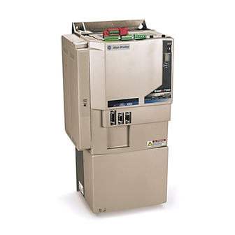
- Page 1 User Manual Kinetix 7000 High Power Servo Drive Catalog Numbers 2099-BM06-S, 2099-BM07-S, 2099-BM08-S, 2099-BM09-S, 2099-BM10-S, 2099-BM11-S, 2099-BM12-S...
- Page 2 Identifies information that is critical for successful application and understanding of the product. Allen-Bradley, CompactLogix, ControlFlash, ControlLogix, DriveExplorer, Kinetix, RSLogix 5000, Rockwell Software, Rockwell Automation, and TechConnect are trademarks of Rockwell Automation, Inc. Trademarks not belonging to Rockwell Automation are property of their respective companies.
- Page 3 Summary of Changes This manual contains new and updated information. Changes throughout this revision are marked by change bars, as shown to the right of this paragraph. New and Updated This table contains the changes made to this revision. Information Topic Page Updated the Additional Resources with updated and new publications.
- Page 4 Summary of Changes Notes: Rockwell Automation Publication 2099-UM001D-EN-P - December 2012...
-
Page 5: Table Of Contents
Table of Contents Preface About This Publication..........9 Who Should Use This Manual . - Page 6 Setting the Ground Jumper in Ungrounded Power Configurations . . . 78 Removing the Ground Jumper on 2099-BM06-S, 2099-BM07-S, and 2099-BM08-S Drives ......... 79 Removing the Ground Wires on 2099-BM09-S and 2099-BM10-S Drives .
- Page 7 Table of Contents Wire the Kinetix 7000 Drive Connectors ......88 Wire the Control Power (CP) Connector ..... . 88 Wire AC Input Power .
- Page 8 Table of Contents Appendix A Specifications and Dimensions Power Specifications ..........150 Circuit Breaker/Fuse Specifications .
-
Page 9: Preface
Preface About This Publication This manual provides detailed installation instructions for mounting, wiring, and troubleshooting your Kinetix 7000 drive, and system integration for your drive/ motor combination with a Logix controller. Who Should Use This Manual This manual is intended for engineers or technicians directly involved in the installation and wiring of the Kinetix 7000 drive, and programmers directly involved in the operation, field maintenance, and integration of the Kinetix 7000 drive with a SERCOS interface module. - Page 10 A glossary of industrial automation terms and abbreviations. You can view or download publications at http://literature.rockwellautomation.com. To order paper copies of technical documentation, contact your local Allen-Bradley distributor or Rockwell Automation® sales representative. Rockwell Automation Publication 2099-UM001D-EN-P - December 2012...
-
Page 11: Start
Chapter Start Use this chapter to become familiar with the design and installation requirements for Kinetix 7000 drive systems. Topic Page About the Drive System Typical Drive System Diagrams Catalog Number Explanation Agency Compliance Rockwell Automation Publication 2099-UM001D-EN-P - December 2012... -
Page 12: About The Drive System
Chapter 1 Start About the Drive System The Kinetix 7000 high-power servo drive is designed to provide a Kinetix Integrated Motion solution for applications with output power requirements in the range of 22…149 kW (40…248 A). Table 1 - Kinetix 7000 Drive System Overview Kinetix 7000 Catalog Numbers Description... -
Page 13: Typical Drive System Diagrams
Start Chapter 1 Typical Drive System Typical Kinetix 7000 system installations include three-phase AC configurations, with and without the line interface module (LIM), and DC common bus Diagrams configurations. Figure 1 - Kinetix 7000 System Configuration with LIM and External Resistive Shunt RSLogix 5000 Software Input Output... - Page 14 2099-BMxx-S Kinetix 7000 Drive Input Power 2090-K6CK-Dxxx Low Profile Connector Kits for I/O, Motor Feedback, and Auxiliary Feedback. Input Fusing 1606-XLxxx Allen-Bradley 1606-XL 24V DC P o we r S u p p ly Control Power Input Control Power Supply Input...
- Page 15 FAULT FAULT PROGRAM PROGRAM 2090-K6CK-Dxxx Low Profile Connector Kits for I/O, Motor and Auxiliary Feedback 1606-XLxxx 24V DC Allen-Bradley 1606-XL Control Power P o we r S u p p ly Input Control Power Supply Input Encoder Motor Feedback Power...
- Page 16 Kits for I/O, Motor and Kits for I/O, Motor and Auxiliary Feedback Auxiliary Feedback 1606-XLxxx 1606-XLxxx 24V DC Allen-Bradley 24V DC Allen-Bradley 1606-XL 1606-XL Po w e r Su p pl y Po w e r Su p p l y...
- Page 17 Low Profile Connector Kits for Low Profile Connector Kits for I/O, Motor Feedback, I/O, Motor Feedback, and Auxiliary Feedback and Auxiliary Feedback. 1606-XLxxx 1606-XLxxx 24V DC 24V DC Allen-Bradley Allen-Bradley 1606-XL 1606-XL Control Power Power Supply Control Power Power Supply Ground Fault...
-
Page 18: Catalog Number Explanation
Kinetix 7000 drive catalog numbers and descriptions are listed in the table below. Drive Kinetix 7000 Cat. No. Kinetix 7000, 460V, 22 kW, 40 A continuous output 2099-BM06-S Kinetix 7000, 460V, 30 kW, 52 A continuous output 2099-BM07-S Kinetix 7000, 460V, 37 kW, 65 A continuous output 2099-BM08-S... -
Page 19: Ce Requirements - System Without Lim
Start Chapter 1 CE Requirements - System without LIM To meet CE requirements when your Kinetix 7000 system does not use a 2094 line interface module to supply AC line and dc control power, the following requirements apply: • Install an 8720MC-RF180 line filter as close to the 8720MC-RPS unit as possible, and the AC line filter (2090-XXLF-TCxxxx) as close to the Kinetix 7000 drive as possible. -
Page 20: Ce Requirements - System With Lim
The full rated current on the AC input line should not exceed that of the line IMPORTANT interface module. Catalog numbers 2094-XL75S-Cx or 2094-BL50S for 2099-BM06-S and 2099-BM07-S Kinetix 7000 drives, or 2094-BL75S for 2099-BM08-S Kinetix 7000 drives. CE requires use of a grounded secondary or source with a 2099-BMxx-S IMPORTANT drive. -
Page 21: Install The Kinetix 7000 Drive System
Chapter Install the Kinetix 7000 Drive System This chapter describes system installation guidelines in preparation for mounting your Kinetix 7000 drive components. Topic Page System Design Guidelines Minimizing Electrical Noise Mount the Kinetix 7000 Drive ATTENTION: Plan the installation of your system so that you can perform all cutting, drilling, tapping, and welding with the system removed from the enclosure. -
Page 22: System Design Guidelines
Chapter 2 Install the Kinetix 7000 Drive System System Design Guidelines To design your enclosure and plan where to mount the system components on the panel, use this section and the information in the Kinetix Servo Drives Specifications Technical Data, publication GMC-TD003. For online product selection and system configuration tools, including AutoCAD (DXF) drawings of the product, go to: http://www.rockwellautomation.com/en/e-tools/. -
Page 23: Circuit Breaker/Fuse Selection
For example: using a secondary of 480 VAC and a 2099-BM06-S with a rated power output = 22 kW continuous: 22 * 1.5 = 33 kVA transformer... -
Page 24: Enclosure Selection
Chapter 2 Install the Kinetix 7000 Drive System Enclosure Selection To assist you in sizing an enclosure, the following example is provided. The example system consists of the following components. • 2-axis Kinetix 7000 servo drive system • ControlLogix chassis and modules Size the Kinetix 7000 servo drive using Motion Analyzer software, version 4.2 or later, and use the results to predict the amount of heat dissipated into the enclosure. - Page 25 Install the Kinetix 7000 Drive System Chapter 2 Table 2 - Kinetix 7000 System Heat Dissipation Example Enclosure Description Loading Heat Dissipation Component (Motion Analyzer) Watts 2099-BM08-S Kinetix 7000 Servo Drive 2099-BM11-S Kinetix 7000 Servo Drive 1275 Total Wattage of Kinetix 7000 system 1727 (1) Loading determined using Motion Analyzer software.
- Page 26 Chapter 2 Install the Kinetix 7000 Drive System In this example, the amount of power dissipated inside the cabinet is the sum of the Kinetix 7000 drive (2099-BM08-S and 2099-BM11-S) system value (1727 W) and the ControlLogix value (34.1 W) for a total of 1761 W. With no active method of heat dissipation (such as fans or air conditioning) either of the following approximate equations can be used.
-
Page 27: Minimum Clearance Requirements
Install the Kinetix 7000 Drive System Chapter 2 Minimum Clearance Requirements This section provides information to assist you in sizing your cabinet and positioning your Kinetix 7000 system components. Mount the module in an upright position as shown. Do not mount the IMPORTANT module on its side. -
Page 28: Minimizing Electrical Noise
Chapter 2 Install the Kinetix 7000 Drive System Minimizing Electrical Noise This section outlines best practices that minimize the possibility of noise-related failures as they apply specifically to Kinetix 7000 drive installations. For more information on the concept of high-frequency (HF) bonding, the ground plane principle, and electrical noise reduction, see the System Design for Control of Electrical Noise Reference Manual, publication GMC-RM001. - Page 29 Install the Kinetix 7000 Drive System Chapter 2 Figure 8 - Recommended Bonding Practices for Painted Panels Stud-mounting the Subpanel Stud-mounting a Ground Bus to the Enclosure Back Wall or Chassis to the Subpanel Subpanel Back Wall of Mounting Bracket or Enclosure Ground Bus Subpanel...
-
Page 30: Bonding Multiple Subpanels
Chapter 2 Install the Kinetix 7000 Drive System Bonding Multiple Subpanels Bonding multiple subpanels creates a common low impedance exit path for the high frequency energy inside the cabinet. Subpanels that are not bonded together may not share a common low impedance path. This difference in impedance may affect networks and other devices that span multiple panels. - Page 31 Install the Kinetix 7000 Drive System Chapter 2 Noise Zones when Using Regenerative Power Supplies (with/without a Line Filter Unit) Observe the following guidelines when laying out a Kinetix 7000 system panel if a regenerative power supply (8720-RPSxxxxx) is used (see Figure 10), and if a regenerative power supply and line filter unit are used (see...
- Page 32 Chapter 2 Install the Kinetix 7000 Drive System Figure 11 - Establishing Noise Zones (Regenerative Power Supply with Line Filter Unit) Clean Wireway (Cx) GPIO, GPR, and SO Cables Dirty Wireway (Dx) Dirty Wireway (Dx) 8720MC-RPS190BM-HV2 Regenerative Power Supply Kinetix 7000 Drive Line Circuit Fuses...
- Page 33 Install the Kinetix 7000 Drive System Chapter 2 AC Power Noise Zones Observe the following guidelines when laying out a Kinetix 7000 system panel, if an AC power supply is used (and regenerative power will not be used). • The clean zone (C) is beneath and left of the Kinetix 7000 drive. This zone includes the motor feedback, auxiliary feedback and registration signals from the IOD connector (grey wireway).
- Page 34 Chapter 2 Install the Kinetix 7000 Drive System 1756-MxxSE SERCOS Interface Module Noise Zones Observe the following guidelines when installing your 1756-MxxSE SERCOS interface module. • The clean zone (C) is beneath the less noisy I/O modules (analog, encoder, registration) - - (grey wireway). •...
-
Page 35: Cable Categories For Kinetix 7000 Systems
Install the Kinetix 7000 Drive System Chapter 2 Cable Categories for Kinetix 7000 Systems The table below indicates the zoning requirements of input power cables connecting to the Kinetix 7000 drive. Table 4 - Kinetix 7000 Drive Wire/Cable Connector Zone Method Very Dirty... -
Page 36: Noise Reduction Guidelines For Drive Accessories
Chapter 2 Install the Kinetix 7000 Drive System Table 6 - Line Interface Module Wire/Cable Connector Zone Method Very Dirty Clean Ferrite Shielde Dirty Sleeve d Cable VAC line (main input) 230V AC input VAC load (shielded option) VAC load (unshielded option) Control power output MBRK PWR, MBRK COM P1L/PSL... - Page 37 Install the Kinetix 7000 Drive System Chapter 2 Shunt Resistor Observe the following guidelines when mounting your external shunt resistor outside the enclosure. • Mount circuit components and wiring in the very dirty zone or in an external shielded enclosure. Run shunt power and fan wiring inside metal conduit to minimize the effects of EMI and RFI.
- Page 38 Chapter 2 Install the Kinetix 7000 Drive System When mounting your shunt module inside the enclosure, follow these additional guidelines. • Metal-clad modules can be mounted anywhere in the dirty zone, but as close to the Kinetix 7000 system as possible. •...
-
Page 39: Mount The Kinetix 7000 Drive
Install the Kinetix 7000 Drive System Chapter 2 Mount the Kinetix 7000 Drive SHOCK HAZARD: To avoid hazard of electrical shock, perform all mounting and wiring of the drive prior to applying power. Once power is applied, connector terminals may have voltage present even when not in use. ATTENTION: Plan the installation of your system so that you can perform all cutting, drilling, tapping, and welding with the system removed from the enclosure. - Page 40 Install the Kinetix 7000 Drive System Figure 16 - Kinetix 7000 Approximate Mounting Dimensions 2099-BM07 shown Dimensions in mm (in.) Kinetix 7000 Drive Cat. No. Mounting Screw Size 2099-BM06-S 517.5 (20.37) 254.12 (10.0) 224.3 (8.83) 495.0 (19.49) 192.0 (7.56) 15.3 (0.60) M6 (0.25)
-
Page 41: Kinetix 7000 Connector Data
Chapter Kinetix 7000 Connector Data This chapter provides power, feedback, and I/O connector locations and signal descriptions for a Kinetix 7000 drive. Topic Page Locate and Identify Connectors and Indicators Control Signal Specifications Control Power Specifications Motor (MF) and Auxiliary Feedback (AF) Connections Rockwell Automation Publication 2099-UM001D-EN-P - December 2012... -
Page 42: Locate And Identify Connectors And Indicators
Chapter 3 Kinetix 7000 Connector Data Locate and Identify Although the physical size of the drives vary, the location of the connectors and indicators is identical. Connectors and Indicators Figure 17 - Kinetix 7000 Front Panel Connectors and Displays SERCOS Node Address SERCOS Node Address... - Page 43 Kinetix 7000 Connector Data Chapter 3 Figure 18 - Kinetix 7000 Top Panel Connectors and Switches 2099-BM08-S shown Top View GPIO GPIO Item Designator/Label Description Connector See Page Safe-off Terminal Block 9-position plug/header GPIO General Purpose I/O Terminal Block 8-position plug/header General Purpose Relay Terminal Block 6-position plug/header SERCOS Fiber-optic Receive Port...
- Page 44 Chapter 3 Kinetix 7000 Connector Data Figure 19 - Kinetix 7000 Bottom Panel Connectors Bottom View 2099-BM06-S and 2099-BM07-S shown Item Designator/Label Description Connector See Page Control Power Terminal Block 2-position terminal Power Terminal Block Access Terminal block Rockwell Automation Publication 2099-UM001D-EN-P - December 2012...
-
Page 45: Digital And Analog Input/Output (Iod) Connector Pinout
Kinetix 7000 Connector Data Chapter 3 Digital and Analog Input/Output (IOD) Connector Pinout The following diagram and table provide the signal description and pin-out information for the 26-pin Digital and Analog Input/Output connector. See Kinetix 7000 Front Panel Connectors and Displays on page for the location of the 26-pin connector. -
Page 46: General Purpose I/O (Gpio) Terminal Block Connections
Chapter 3 Kinetix 7000 Connector Data General Purpose I/O (GPIO) Terminal Block Connections The following diagram and table provide the orientation and signal description for the General Purpose Input/Output terminal block. Figure 21 - Orientation for General Purpose I/O (GPIO) Terminal Block GPIO Table 9 - General Purpose I/O (GPIO) Terminal Block Terminal... -
Page 47: Motor Feedback (Mf) Connector Pinouts
Kinetix 7000 Connector Data Chapter 3 Motor Feedback (MF) Connector Pinouts The following diagram and tables provide the orientation and signal description for the Motor Feedback (MF) connector for each applicable feedback device. Figure 23 - Pin Orientation for 15-pin Motor Feedback (MF) Connector Pin 10 Pin 15 Pin 5... - Page 48 Chapter 3 Kinetix 7000 Connector Data Kinetix 7000 drives do not natively support Heidenhain EnDat high-resolution feedback. However, you can use the drive motor feedback connection with the 2090-K7CK-KENDAT feedback module to convert Heidenhain EnDat 2.1 high-resolution feedback from an RDD motor. Use the table below to connect the motor feedback wires to the 2090-K7CK-KENDAT feedback module.
-
Page 49: Auxiliary Feedback (Af) Connector Pinouts
Kinetix 7000 Connector Data Chapter 3 Auxiliary Feedback (AF) Connector Pinouts For TTL devices, the position count will increase when A leads B. For sinusoidal devices, the position count will increase when cosine leads sine. Figure 24 - Pin Orientation for 15-pin Auxiliary Feedback (AF) Connector Pin 6 Pin 11 Pin 1... -
Page 50: Safe-Off (So) Terminal Block Connections
Chapter 3 Kinetix 7000 Connector Data Safe-off (SO) Terminal Block Connections Figure 25 - Safe-off (SO) Terminal Block Table 16 - Safe-off (SO) Terminal Block Terminal Description Signal Name Normally-closed monitoring contact for safety relay 2 FDBK2+ Return for safety relay 2 FDBK2- Normally-closed monitoring contact for safety relay 1 FDBK1+... -
Page 51: Control Power (Cp) Terminal Block Connections
2099-BM09-S and 2099-BM10-S, and 138 VA for the 2099-BM11-S and 2099- BM12-S drives. The 2099-BM06-S, 2099-BM07-S, and 2099-BM08-S drives (frame 3) use the internal power supply for fan power and thus no terminals are provided. Rockwell Automation Publication 2099-UM001D-EN-P - December 2012... - Page 52 Chapter 3 Kinetix 7000 Connector Data Figure 27 - 2099-BM06-S, 2099-BM07-S, and 2099-BM08-S Cable clamps for Motor and AC inputs. Figure 28 - 2099-BM09-S Fan Terminals Enlarged View Motor AC Line Figure 29 - 2099-BM10-S Fan Terminals Enlarged View Motor...
- Page 53 Kinetix 7000 Connector Data Chapter 3 Figure 30 - 2099-BM11-S and 2099-BM12-S Fan Terminals Enlarged View Motor AC Line Table 18 - Power Terminal Block Terminal Description Name DC Bus Power DC Bus (+) DC Bus (-) Main Ground of the Drive System PE Ground Motor Ground Motor Ground...
-
Page 54: Control Signal Specifications
Chapter 3 Kinetix 7000 Connector Data Control Signal Specifications This section provides specifications for the Kinetix 7000 drive input/output (IOD), SERCOS, motor feedback (MF), auxiliary feedback (AF) and brake (BC) connectors. Digital Inputs (IOD Connector) Two fast registration inputs and four other inputs are available for the machine interface on the Kinetix 7000 drive. - Page 55 Kinetix 7000 Connector Data Chapter 3 Hardware Enable The Hardware Enable input is an optically isolated (500V), single-ended, active high signal. A 24V DC input applied to this pin enables the drive. The status of this digital input can be monitored in the axis servo drive tag in RSLogix.
- Page 56 Chapter 3 Kinetix 7000 Connector Data Home The Home input is an optically isolated (500V), single-ended, active high signal. A 24V DC input applied to this pin by a normally-open contact indicates this axis is in the home position. Firmware provides an additional 50 ms of debounce. You can configure the required Home type in the axis servo drive properties in RSLogix.
- Page 57 Kinetix 7000 Connector Data Chapter 3 Positive and Negative Overtravel The Positive and Negative Overtravel detection is provided by two optically isolated (500V), single-ended, normally-closed, active high signals. Breaking the 24V DC input at either pin indicates an overtravel condition. You can enable hard travel limits on the axis servo drive Limit tab in RSLogix.
- Page 58 Chapter 3 Kinetix 7000 Connector Data Registration The two fast Registration inputs are provided on the Kinetix 7000 drive, Reg 1 (IOD-14) and Reg 2 (IOD-17). Unlike the Drive Enable, Home, and Overtravel signals, these inputs are either positive-edge or negative-edge triggered. They are based on the user-defined MAR (Motion Axis Registration) configured using RSLogix software.
- Page 59 Kinetix 7000 Connector Data Chapter 3 Figure 36 - Registration Digital Input Circuit Diagram +24V DC IOD-13, or -16 I/O SUPPLY IOD-14, or -17 INPUT 1k Ω 3k Ω REG_INPUT 0.001 μF 511 Ω IOD-15, or -18 HCPL-0631 IO_COM Customer-Supplied Kinetix 7000 Drive Registration Input Device (1) +24V DC source (range) = 21.6V…26.4V (supplied by the drive, not to exceed 300 mA total).
-
Page 60: Analog Inputs (Iod Connector)
Chapter 3 Kinetix 7000 Connector Data Analog Inputs (IOD Connector) RSLogix 5000 software, version 15, does not support analog input IMPORTANT utilization. Two analog inputs are provided, with 14-bit resolution (13 data bits, plus sign). The analog data streamed to RSLogix by these inputs is useful for managing dynamic machine operations, for example tension transducers in an outer tension control loop. - Page 61 Kinetix 7000 Connector Data Chapter 3 Reading Analog Input Voltage Values When connecting to the Kinetix 7000 drive via DriveExecutive or DriveExplorer, the input voltage is displayed as a percentage in parameters 691 [AnaInput 1 Value] and 692 [AnaInput 2 Value]. In the example above, analog input 1 displays 69.79%.
-
Page 62: Analog Outputs (Iod Connector)
Chapter 3 Kinetix 7000 Connector Data Analog Outputs (IOD Connector) The two analog outputs (Analog_Out_1 and Analog_Out_2) are strictly for troubleshooting and cannot be used to drive other loads. The analog outputs provide 12-bit resolution (11 data bits, plus sign) of the gain and filtering parameters within RSLogix software. -
Page 63: General Purpose I/O (Gpio Connector)
Kinetix 7000 Connector Data Chapter 3 General Purpose I/O (GPIO Connector) Two 24V digital outputs are user programmable. You can monitor the status the an optional regenerative power supply. An isolated, external 24V DC power source must be customer supplied to power the digital outputs. Table 21 - General Purpose I/O Digital Output Specifications Signal Description... -
Page 64: General Purpose Relay (Gpr Connector)
Chapter 3 Kinetix 7000 Connector Data The regenerative power supply OK provides status on the regenerative converter; in doing so, provides status to the Kinetix 7000 drive that there is DC bus power. Selecting the 8720MC-RPSxxx on the Power tab in the Kinetix 7000 drive I/O configuration in RSLogix requires the customer to provide a 24V DC power source to GPIO pins 7 and 8 as shown in Table 22... -
Page 65: Sercos Connections
Kinetix 7000 Connector Data Chapter 3 SERCOS Connections Two fiber-optic connectors (transmit and receive) are provided on the Kinetix 7000 drive. Table 24 - SERCOS Communications Specifications Specification Description Data Rates 4 and 8 Mbps Node Addresses 01…99 (1) Node addresses for additional axes on the same system are assigned by sequentially incrementing each additional axis. See Node Addressing Examples on page for more information. -
Page 66: Motor (Mf) And Auxiliary Feedback (Af) Connections
Motor feedback requires RSLogix 5000 motion.db file to properly commutate the motor. Motors available in RSLogix software include feedback types designated as S and M in Allen-Bradley catalog numbers. Following are further definitions of these feedback types. • S type - single-turn 1024 cycles per rotation (interpolated to over 2 million counts in the drive) For example, the MPL-B980D-SJ72AA has this feedback type. - Page 67 Kinetix 7000 Connector Data Chapter 3 Figure 42 - AM, BM, and IM Motor Encoder Inputs +5 V 1k Ω 10k Ω 1k Ω 56 pF 1k Ω 56 pF 1k Ω 56 pF 100 pF 1k Ω 10k Ω 1k Ω...
- Page 68 Chapter 3 Kinetix 7000 Connector Data Parameter Description Minimum Maximum IM Pulse Width Pulse width of the index input signal. Since the index 125 nS — is active for a percentage of a revolution, the speed will determine the pulse width. AM, BM Phase Error Amount that the phase relationship between the AM -22.5°...
- Page 69 Kinetix 7000 Connector Data Chapter 3 • See the Kinetix Motion Control Selection Guide, publication GMC- SG001, for cables compatible with the Kinetix 7000 drive and motor. • Low profile connector let you develop a custom cable for the Motor Feedback (MF) or Auxiliary Feedback (AF) connectors.
- Page 70 Chapter 3 Kinetix 7000 Connector Data Notes: Rockwell Automation Publication 2099-UM001D-EN-P - December 2012...
-
Page 71: Connect The Kinetix 7000 Drive System
Chapter Connect the Kinetix 7000 Drive System This chapter provides procedures for wiring your Kinetix 7000 drive system components and making cable connections. Topic Page Basic Wiring Requirements Determine the Input Power Configuration Setting the Ground Jumper in Ungrounded Power Configurations Grounding the Kinetix 7000 Drive System Input Power Wiring Requirements Power Wiring Guidelines... -
Page 72: Building Your Own Motor Cables
Chapter 4 Connect the Kinetix 7000 Drive System Building Your Own Motor Cables Factory-made cables are designed to minimize EMI and are recommended IMPORTANT over hand-built cables to optimize system performance. • Connect the cable shield to the connector shells on both ends of the cable with a complete 360°... -
Page 73: Cable Sizes
Connect the Kinetix 7000 Drive System Chapter 4 Cable Sizes In the table below the appropriate VFD shielded cable to use based on 150% overload capability and 25 °C (77 °F) operating temperature is shown. For applications above 130 Amps, use thick insulation lead wire, such as RHW-2 or equal. -
Page 74: General Wire Guidelines
Chapter 4 Connect the Kinetix 7000 Drive System General Wire Guidelines Observe all applicable safety and national and local regulations when selecting the appropriate wire size for your system. Due to the drive overload capacity of 150% of the continuous current rating, the conductors for the transformer primary and secondary must be sized (at a minimum) for 125…160% of the maximum continuous input current for the motor selected. -
Page 75: Determine The Input Power Configuration
Connect the Kinetix 7000 Drive System Chapter 4 Determine the Input Power Before wiring input power to your Kinetix 7000 drive system you must determine the type of input power to which you are connecting. The Kinetix 7000 drive is Configuration configured at the factory to operate in a grounded power environment. - Page 76 Chapter 4 Connect the Kinetix 7000 Drive System This is an example of a grounded B-phase (delta secondary). Figure 45 - Grounded B-phase Power Wiring - Delta Secondary 2099-BM08-S Shown with Lower Front Panel Removed Transformer (Delta) Secondary Transformer Line Filter Bonded Cabinet Ground To Ground Stud...
-
Page 77: Power Distribution Systems Without A Ground Reference
Connect the Kinetix 7000 Drive System Chapter 4 Power Distribution Systems Without a Ground Reference Kinetix 7000 drives contain protective MOVs and Common Mode Capacitors that are referenced to ground. To guard against unstable operation and/or drive damage, these devices must be disconnected if the drive is installed on an ungrounded, impedance grounded, high resistive grounded, B phase grounded, or common DC bus power distribution system. -
Page 78: Setting The Ground Jumper In Ungrounded Power Configurations
Component Location 2099-BM06-S, 2099-BM07-S and Common mode capacitor Remove the two jumpers located above the power terminal block. See 2099-BM08-S Removing the Ground Jumper on 2099-BM06-S, 2099-BM07-S, and 2099- BM08-S Drives on page MOVs 2099-BM09-S and Green/yellow Common mode capacitor... -
Page 79: Removing The Ground Jumper On 2099-Bm06-S, 2099-Bm07-S, And 2099-Bm08-S Drives
1 (PEA) and the MOV jumper is indicated by callout 2 (PEB). Remove each jumper by carefully pulling it straight out. Figure 47 - Ground Jumper Location on 2099-BM06-S, 2099-BM07-S, and 2099-BM08-S PE B CM Cap... -
Page 80: Removing The Ground Wires On 2099-Bm09-S And 2099-Bm10-S
Chapter 4 Connect the Kinetix 7000 Drive System Removing the Ground Wires on 2099-BM09-S and 2099-BM10-S Drives Figure 48 shows the locations of the common mode capacitor and MOV/input filter capacitor ground wires in 2099-BM09-S and 2099-BM10-S drives. The common mode capacitor ground wire is indicated by callout 3 and the MOV/ input filter cap ground wire is indicated by callout 4. -
Page 81: Grounding The Kinetix 7000 Drive System
Connect the Kinetix 7000 Drive System Chapter 4 Grounding the Kinetix 7000 All equipment and components of a machine or process system must have a common earth ground point connected to their chassis. Drive System A grounded system provides a ground path for short-circuit protection. Grounding your modules and panels minimize shock hazard to personnel and damage to equipment caused by short-circuits, transient overvoltages, and accidental connection of energized conductors to the equipment chassis. -
Page 82: Grounding Multiple Subpanels
A small portion of the cable jacket must be removed to expose the shield braid. The exposed area must be clamped (using the clamp provided on the 2099-BM06-S, -BM07-S and -BM08-S drives) to the drive to provide a 360° termination. Factory-supplied power cables must also be terminated in the motor power (MP) connector plug. -
Page 83: Mp-Series (Bulletin Mpl) Motor Connectors
Connect the Kinetix 7000 Drive System Chapter 4 Figure 52 - Power Cable Shielding Techniques Recommended for Kinetix 7000 Drives Drive Conduit or Cable Braid Clamped at Drive Frame Provides 360° Shield Termination. Clamp Also Connects to the Nearest Available Bonded Cabinet Ground. Enclosure Junction Box Beneath Drive... - Page 84 Chapter 4 Connect the Kinetix 7000 Drive System Table 32 - Motor Power Cable Compatibility Motor/Actuator Connector Motor/Actuator Cat. No. Motor Power Cables Motor Power Cables (with brake wires) (without brake wires) MP-Series (Bulletin MPL) Circular DIN MPL-B5xxx, MPL-B6xxx, MPL-B8xxx, and 2090-CPBM7DF-xxAAxx or 2090-CPWM7DF-xxAAxx MPL-B9xxx...
-
Page 85: Input Power Wiring Requirements
Connect the Kinetix 7000 Drive System Chapter 4 Input Power Wiring National codes and standards (NEC, VDE, BSI etc.) and local codes outline provisions for safely installing electrical equipment. Installation must comply Requirements with specifications regarding wire types, conductor sizes, branch circuit protection and disconnect devices. -
Page 86: Contactors
Chapter 4 Connect the Kinetix 7000 Drive System A good example of recommended cable is Belden/E 295xx (xx determines gauge). This cable has four XLPE insulated conductors with a 100% coverage foil and an 85% coverage copper braided shield (with drain wire) surrounded by a PVC jacket. -
Page 87: Power Wire Specifications
Connect the Kinetix 7000 Drive System Chapter 4 Power Wire Specifications Wire should be copper with 75 °C (167 °F) minimum rating. Phasing of main AC power is arbitrary and earth ground connection is required for safe and proper operation. For additional information see Power Specifications on page 150, and Interconnect Diagram Notes on page for interconnect diagrams. -
Page 88: Power Wiring Guidelines
Chapter 4 Connect the Kinetix 7000 Drive System Power Wiring Guidelines Use these guidelines when wiring the power connectors on your Kinetix 7000 drive (without a LIM). To achieve system performance, run wires and cables in the wireways as IMPORTANT established in Chapter To limit coil switching transients generated by the LINE contactor, use of a... -
Page 89: Wire Ac Input Power
Table 35 - AC Input Power Connections Kinetix 7000 Signal Terminal Recommended Wire Size Torque Drive Cat. No. (AWG) m (lb • • 2099-BM06-S 2099-BM07-S 25…2.5 (3…14) 1.8 (16) 2099-BM08-S Ground 2099-BM09-S 50…4 (1/0…12) 3.6 (32) Ground 50…4 (1/0…12) 5 (44) 2099-BM10-S 70…10 (2/0…8) -
Page 90: Wire The Safe-Off (So) Connector
Table 36 - DC Input Power Connections Kinetix 7000 Signal Description Terminal(s) Recommended Wire Size Torque Drive Cat. No. (AWG) m (lb • • 2099-BM06-S 2099-BM07-S 25…2.5 (3…14) 1.8 (16) 2099-BM08-S 2099-BM09-S 50…4 (1/0…12) 3.6 (32) 2099-BM10-S 70…10 (2/0…8) 15 (133) 2099-BM11-S 100…10 (4/0…8) -
Page 91: (Gpio) Connectors
Connect the Kinetix 7000 Drive System Chapter 4 Wire the General Purpose Relay (GPR) and General Purpose I/O (GPIO) Connectors Wire the control and interface signals on the General Purpose Relay (GPR) and General Purpose I/O (GPIO) connectors as described in Table 38 Table See General Purpose I/O (GPIO) Terminal Block Connections on page... -
Page 92: Wire Motor Output Power
Table 40 - HPK-Series and MP-Series Servo Motor Power Connections Kinetix 7000 Signal Terminal Recommended Wire Size Torque Drive Cat. No. (AWG) m (lb • • 2099-BM06-S U / Brown 2099-BM07-S V / Black 25…2.5 (3…14) 1.8 (16) 2099-BM08-S w / Blue Green/Yellow 2099-BM09-S U / Brown V / Black 50…4 (1/0…12) -
Page 93: Feedback And I/O Cable Connections
Connect the Kinetix 7000 Drive System Chapter 4 Motor brake wiring varies slightly, depending on the motor connector type. The table below identifies the brake wire option for your servo motor and the appropriate brake cable or connector kit catalog number required. Motor Series Connector Brake Wire Option... -
Page 94: Flying-Lead Feedback Cable Pinouts
Chapter 4 Connect the Kinetix 7000 Drive System Flying-lead Feedback Cable Pinouts Table 44 - 2090-XXxFMP-Sxx Feedback Cable Motor Bayonet Rotary Motors with High Resolution Feedback: Drive MF Connector Pin MPL-B5xxxx-M/Sx2xAA, MPL-B6xxxx-M/Sx2xAA, Connector Pin MPL-B8xxxx-M/Sx2xAA, and MPL-B9xxxx-M/Sx2xAA Signal Sine+ Sine- Cos+ Cos- Data+... -
Page 95: Wire Feedback And I/O Connectors
Connect the Kinetix 7000 Drive System Chapter 4 Table 46 - 2090-XXNFMF-Sxx and 2090-CFBMxDF-CDAFxx Feedback Cable Motor Circular DIN RDB-Bxxxxx-3/7 Motors 2090-K7CK-KENDAT Connector Pin Signal Sine+ Sine- Cos+ Cos- Data+ Data- CLK+ CLK- EPWR_5V ECOM Reserved – Reserved – – Reserved –... -
Page 96: Wire Panel-Mounted Breakout Board Kits
Chapter 4 Connect the Kinetix 7000 Drive System Figure 54 - Premolded Motor Feedback Cable Connection Kinetix 7000 Drive (Side View) Premolded Connector Cable: 2090-CFBM7DD-CEAAxx (standard, non-flex) 2090-CFBM7DD-CEAFxx (continuous flex) Wire Panel-mounted Breakout Board Kits The panel-mounted breakout board kit (catalog number 2090-UXBK-D15xx) includes a (DIN rail) terminal block and cable. - Page 97 Connect the Kinetix 7000 Drive System Chapter 4 Figure 55 - Panel-mounted Breakout Board Connection Example Kinetix 7000 Drive (Side View) See the Motor Feedback Breakout Board Installation Instructions, publication 2090-IN006, for Connector Breakout Board Specifications. 2090-UXBC-D15xx 2090-UXBB-D15xx Breakout Cable Panel-mounted Breakout Board Rockwell Automation Publication 2099-UM001D-EN-P - December 2012...
-
Page 98: Wire Low-Profile Connectors
Chapter 4 Connect the Kinetix 7000 Drive System Wire Low-profile Connectors Low-profile connectors (2090-K6CK-Dxxx) are suitable for motor feedback (MF), auxiliary feedback (AF), and I/O connections (IOD) on Kinetix 7000 drive. Table 47 - Low-profile Connector Kits Connector Kit Description Cable Compatibility Cat. - Page 99 Connect the Kinetix 7000 Drive System Chapter 4 Figure 56 - Wiring (15-pin) Flying-lead Feedback Cable Connections 2090-K6CK-D15M and 2090-K6CK-D15F Connector Kits 15-pin (male) Motor Feedback 15-pin (female) Auxiliary Feedback Low-profile Connector Low-profile Connector Bare wires Wire insulation Pin 10 Pin 6 Mounting Pin 15...
- Page 100 Chapter 4 Connect the Kinetix 7000 Drive System Figure 58 - Wiring (26-pin) I/O Cable Connections 2090-K6CK-D26M Connector Kit Pin 18 Pin 9 Pin 26 Mounting Screws Pin 19 Pin 1 Pin 10 26-pin (male) I/O Low-profile Connector See the Low Profile Connector Kit Installation 2090-K6CK-D26M Instructions, Publication Low-profile Connector Kit...
-
Page 101: External Shunt Module Connections
Connect the Kinetix 7000 Drive System Chapter 4 External Shunt Module External active shunt modules listed in the table on page 156 are compatible with Kinetix 7000 drives. Follow these guidelines when wiring your external active Connections shunt module kit. •... - Page 102 Chapter 4 Connect the Kinetix 7000 Drive System Figure 59 - CompactLogix, ControlLogix, and SoftLogix SERCOS Connector Locations SERCOS interface CompactLogix Platform ControlLogix Platform 1768-M04SE SERCOS 1756-MxxSE SERCOS interface Module interface Module SoftLogix Platform 1756-PM16SE SERCOS interface PCI Card (as viewed from the back of your personal RSLogix 5000 Software computer) Front View...
- Page 103 Connect the Kinetix 7000 Drive System Chapter 4 The following fiber-optic cable examples are shown using ControlLogix modules. CompactLogix modules connect in the same way, however the ring cannot include more than four drives. Figure 61 - Fiber-optic Cable Connections to ControlLogix/CompactLogix Modules 1756-MxxSE SERCOS interface Module Logix Chassis SERCOS interface...
- Page 104 Chapter 4 Connect the Kinetix 7000 Drive System The following example depicts the second Kinetix system, consisting of Kinetix 7000 drives, located in a separate cabinet and connected with bulkhead adapters. To avoid signal loss, do not use bulkhead adapters to connect glass cables. IMPORTANT Use bulkhead adapters for making plastic-to-plastic cable connections only.
-
Page 105: Configure And Startup The Kinetix 7000 Drive System
Chapter Configure and Startup the Kinetix 7000 Drive System This chapter provides procedures for configuring your Kinetix 7000 system components with the Logix SERCOS module. Topic Page Configure the Drive Modules Configure the Logix SERCOS interface Module Apply Power to the Drive Test and Tune the Axes Configure Drive Parameters and System Variables Before you begin, make sure you know the characteristics of the following system... -
Page 106: Configure The Drive Modules
Chapter 5 Configure and Startup the Kinetix 7000 Drive System Configure the Drive Modules Follow these steps to configure the Kinetix 7000 drive. 1. Verify that there is no power applied to the drive and that the SERCOS fiber-optic cables are plugged into the Tx and Rx connectors. To verify your fiber-optic cable connections, refer to page 101. - Page 107 Configure and Startup the Kinetix 7000 Drive System Chapter 5 5. Set the SERCOS optical power level to High using DIP switch 1. For This Optical Power Level Set Switch 1 High IMPORTANT All drives on the SERCOS ring must have the same baud rate and power setting. Figure 64 - SERCOS DIP Switch Settings and Locations DIP Switches Set for DIP Switches Set for...
-
Page 108: Node Addressing Examples
Chapter 5 Configure and Startup the Kinetix 7000 Drive System Node Addressing Examples The examples below illustrate how each axis in the fiber-optic ring is assigned a node address. The ControlLogix platform is used in the examples, but the node addressing is typical for Logix platforms. - Page 109 Configure and Startup the Kinetix 7000 Drive System Chapter 5 Figure 66 - Node Addressing Example 2 1756-MxxSE SERCOS interface Module SERCOS interface Logix Chassis/PCI Card (ControlLogix chassis is shown) Tx (rear) Rx (front) Transmit Receive SERCOS Fiber-optic Ring Kinetix 6000 Kinetix 7000 (8-axis power rail) (2-axis)
-
Page 110: Configure The Logix Sercos Interface Module
Chapter 5 Configure and Startup the Kinetix 7000 Drive System Configure the Logix SERCOS This procedure assumes that you have wired your Kinetix 7000 system and set the Kinetix 7000 baud rate and optical power switches. interface Module For the Kinetix 7000 drive to communicate with the SERCOS interface module IMPORTANT (indicated by three solid-green status indicators on the SERCOS module), your RSLogix 5000 software must be revision 15.0 or later. - Page 111 Configure and Startup the Kinetix 7000 Drive System Chapter 5 The Controller Properties dialog box opens. 6. Click the Date/Time tab. 7. Check Enable Time Synchronization. This assigns the controller as the Grandmaster clock. The motion modules set their clocks to the module you assign as the Grandmaster. You can assign only one module in the Logix chassis as the IMPORTANT Grandmaster clock.
-
Page 112: Configure The Sercos Module
Chapter 5 Configure and Startup the Kinetix 7000 Drive System Configure the SERCOS Module Follow these steps to configure the SERCOS module. 1. Right-click on I/O Configuration in the Controller Organizer and choose New Module. The Select Module dialog box opens. 2. - Page 113 Configure and Startup the Kinetix 7000 Drive System Chapter 5 Your new module appears under the I/O Configuration folder in the Controller Organizer and the Module Properties dialog box opens. 6. Click the SERCOS Interface tab and reference the table below. Logix SERCOS Module Number of Axes Data Rate...
-
Page 114: Configure The Motion Group
Chapter 5 Configure and Startup the Kinetix 7000 Drive System Configure the Motion Group Follow these steps to configure the motion group. 1. Right-click Motion Groups in the Controller Organizer and choose New Motion Group. The New Tag dialog opens. 2. - Page 115 Configure and Startup the Kinetix 7000 Drive System Chapter 5 No axis have been created yet. For this setup, a servo axis named Axis_1 and a feedback only axis named Axis_1_Aux will be created. Both axes will be assigned to the Kinetix 7000 axis in the Configure the Kinetix 7000 Drive Modules section.
- Page 116 Chapter 5 Configure and Startup the Kinetix 7000 Drive System Both Axis_1 and Axis_1_Aux are Assigned to the Motion Group. This means both axis will be part of the SERCOS and Motion planner updates from/to the controller/SERCOS card/drive. 11. Open the Attribute folder. The Motion Planner coarse update period must be set according to the application needs.
-
Page 117: Configure The Kinetix 7000 Drive Modules
Configure and Startup the Kinetix 7000 Drive System Chapter 5 Configure the Kinetix 7000 Drive Modules Follow these steps to configure the Kinetix 7000 drive modules. 1. Right-click the Logix module you just created and choose New Module. The Select Module dialog box opens. 2. - Page 118 Chapter 5 Configure and Startup the Kinetix 7000 Drive System Set the node address in the software to match the node setting on the drive. Refer to Configure the Drive Modules, step 2, on page 106. c. Check Open Module Properties. 5.
- Page 119 Configure and Startup the Kinetix 7000 Drive System Chapter 5 12. Select the Conversion tab. Based on the type of application, the system can be configured for a linear or rotary system. To simplify the setup, a linear system is utilized. The calculate tool on the Drive/Motor tab will be used to set the drive resolution and conversion constant.
- Page 120 Chapter 5 Configure and Startup the Kinetix 7000 Drive System 16. The Change Catalog Number dialog box appears. 17. Select the appropriate motor catalog number for your application. It is important to verify the motor catalog number on the motor nameplate as well as in your design specification.
- Page 121 Configure and Startup the Kinetix 7000 Drive System Chapter 5 The Drive/Motor tab and Conversion tabs should look similar to these examples or reflect your application configuration. Rockwell Automation Publication 2099-UM001D-EN-P - December 2012...
- Page 122 Chapter 5 Configure and Startup the Kinetix 7000 Drive System 24. Click the Fault Actions tab. 25. Click Set Custom Stop Action. The Custom Stop Action Attributes dialog box opens and lets you set delay times for servo motors with a brake and resistive brake modules. For recommended motor brake delay times, refer to refer to the Kinetix Motion Control Selection Guide, publication GMC-SG001.
- Page 123 Configure and Startup the Kinetix 7000 Drive System Chapter 5 Axis_1_Aux is configured similar to Axis_1, except that only a feedback device is configured. 29. Configure the Auxiliary Axis properties. Click next to Axis_1_Aux. The Axis Properties dialog box opens on the General tab. If an axis is associated to the auxiliary axis node, set the Axis Configuration on the General tab of the Axis Properties dialog box to Feedback Only.
- Page 124 Chapter 5 Configure and Startup the Kinetix 7000 Drive System 33. Configure the drive resolution / conversion constant (position unwind, if rotary) as in step 19…22 of this procedure. 34. Click the Aux Feedback tab. The Aux Feedback tab must be configured for the auxiliary IMPORTANT feedback type being used.
-
Page 125: Download The Program
Configure and Startup the Kinetix 7000 Drive System Chapter 5 39. From the Bus Regulator Configuration pull-down menu, choose the component appropriate for your actual hardware configuration. Note: The Kinetix 7000 drive internal dynamic brake IGBT is not utilized by the drive main control for bus regulation therefore any type of regulation must come from an external source. -
Page 126: Apply Power To The Drive
Chapter 5 Configure and Startup the Kinetix 7000 Drive System Apply Power to the Drive This procedure assumes that you have completed the following tasks: • Wired your Kinetix 7000 drive. • Connected your Logix controller, SERCOS interface module fiber-optic connections to your Kinetix 7000 drive. - Page 127 Configure and Startup the Kinetix 7000 Drive System Chapter 5 3. Define the three-phase input power as described below. If Your Three-phase Power Then 1. Set the LIM CB1 to the ON position. 2. Verify that the LIM, IPL, and OPL connections for phase-to- phase voltage is 324…528V AC (460V).
- Page 128 Chapter 5 Configure and Startup the Kinetix 7000 Drive System 5. Observe the three status indicators on the front of the drive. Status Indicator Condition Status Do This Normal condition Observe the Comm status LED. Drive Steady red Drive is faulted Go to Status Indicators on page 143.
-
Page 129: Test And Tune The Axes
Configure and Startup the Kinetix 7000 Drive System Chapter 5 Test and Tune the Axes This procedure assumes that you have configured your Kinetix 7000 drive, your SERCOS interface module, and applied power to the system. For help using RSLogix 5000 software as it applies to testing and tuning your axes with ControlLogix, CompactLogix, or SoftLogix SERCOS modules, refer to Additional Resources on page 9. - Page 130 Chapter 5 Configure and Startup the Kinetix 7000 Drive System 4. Type 2.0 as the number of revolutions for the test or another number more appropriate for your application. This Test Performs this Test Test Marker Verifies marker detection capability as you rotate the motor shaft. Verifies feedback connections are wired correctly as you rotate the Test Feedback motor shaft.
-
Page 131: Tune The Axes
Configure and Startup the Kinetix 7000 Drive System Chapter 5 9. Determine if your test completed successfully. Then Your test completes successfully, this dialog box opens. 1. Click OK. 2. Remove Hardware Enable Input signal (IOD-2). 3. Go to Tune the Axes on page 131. Your test failed, this dialog box opens. - Page 132 Chapter 5 Configure and Startup the Kinetix 7000 Drive System 3. Enter values for Travel Limit and Speed. In this example, Travel Limit = 5 and Speed = 10. The actual value of programmed units depend on your application. 4. From the Direction pull-down menu, choose a setting (Forward Uni- directional is default).
- Page 133 Configure and Startup the Kinetix 7000 Drive System Chapter 5 The Online Command - Apply Tune dialog box opens. When the test completes, the Command Status changes from Executing to Command Complete. 11. Click OK. 12. Determine if your test completed successfully. Then Your test completes successfully, this dialog box opens.
-
Page 134: Configure Drive Parameters And System Variables
Chapter 5 Configure and Startup the Kinetix 7000 Drive System Configure Drive Parameters This section provides information for accessing and changing parameters not accessible through RSLogix 5000 software. and System Variables Tools for Changing Parameters Most parameters are accessible through RSLogix 5000 software. Alternatives include the DPI compatible Human Interface Module (HIM), and DriveExplorer and DriveExecutive software. - Page 135 Configure and Startup the Kinetix 7000 Drive System Chapter 5 Change Parameters with the HIM Module When using the HIM module to monitor or change parameters, use the up and down arrows (∧ and ∨ ) to arrive at selections. Refer to the instructions that came with your HIM module for more information.
- Page 136 Chapter 5 Configure and Startup the Kinetix 7000 Drive System Notes: Rockwell Automation Publication 2099-UM001D-EN-P - December 2012...
-
Page 137: Troubleshoot The Kinetix 7000 Drive System
Chapter Troubleshoot the Kinetix 7000 Drive System This chapter provides troubleshooting tables for your Kinetix 7000 system components. Topic Page Safety Precautions Interpret Error Codes and Status Indicators General System Anomalies Logix/Drive Fault Behavior Equipment connected to the Kinetix 7000 drive may store error data, and IMPORTANT may take precedence when troubleshooting the system. -
Page 138: Interpret Error Codes And Status Indicators
Chapter 6 Troubleshoot the Kinetix 7000 Drive System Interpret Error Codes and Refer to these troubleshooting tables to identify faults, potential causes, and the appropriate actions to resolve the fault. If the fault persists after attempting to Status Indicators troubleshoot the system, please contact your Rockwell Automation sales representative for further assistance. - Page 139 Troubleshoot the Kinetix 7000 Drive System Chapter 6 Table 50 - Seven-segment Status Indicator Error Codes (Continued) Error Fault Message RSLogix Anomaly or Symptom Potential Cause Possible Resolution Code Verify continuity of motor power cable and Motor cables shorted. connector. Disconnect motor power cables from the motor.
- Page 140 Chapter 6 Troubleshoot the Kinetix 7000 Drive System Table 50 - Seven-segment Status Indicator Error Codes (Continued) Error Fault Message RSLogix Anomaly or Symptom Potential Cause Possible Resolution Code Check cables for noise. Motor speed has exceeded 150% of maximum rated speed. The 100% trip Check tuning.
- Page 141 Troubleshoot the Kinetix 7000 Drive System Chapter 6 Table 50 - Seven-segment Status Indicator Error Codes (Continued) Error Fault Message RSLogix Anomaly or Symptom Potential Cause Possible Resolution Code The SERCOS ring is not active Check that fiber-optic cable is present and properly SERCOSFault after being active and Cable disconnected.
- Page 142 Chapter 6 Troubleshoot the Kinetix 7000 Drive System Table 50 - Seven-segment Status Indicator Error Codes (Continued) Error Fault Message RSLogix Anomaly or Symptom Potential Cause Possible Resolution Code Load default parameters, save to nonvolatile memory, and recycle power or reset the drive. DriveHardFault Nonvolatile memory is corrupt due to control board hardware failure.
-
Page 143: Status Indicators
Troubleshoot the Kinetix 7000 Drive System Chapter 6 Status Indicators Table 51 - Drive Status Indicator Drive Status LED Status Potential Cause Possible Resolution Normal, no faults Steady Red Drive faulted Seven-segment status indicator displays error code. See the Error Codes on page section and continue troubleshooting. -
Page 144: General System Anomalies
Chapter 6 Troubleshoot the Kinetix 7000 Drive System Table 54 - SERCOS Status Indicator SERCOS Status Status Condition Actively cycling The drive is looking for a closed SERCOS ring. Wait Check fiber-optic connections. for phase 1 to complete or take corrective action Serial ring must enter at the Rx connector and exit TX connector. - Page 145 Troubleshoot the Kinetix 7000 Drive System Chapter 6 Condition Potential Cause Possible Resolution Torque Limit limits are set too low. Verify that current limits are set properly. Incorrect motor selected in configuration. Select the correct motor and run Tune in RSLogix 5000 software. •...
-
Page 146: Logix/Drive Fault Behavior
Chapter 6 Troubleshoot the Kinetix 7000 Drive System Condition Potential Cause Possible Resolution Motor tuning limits are set too high. Run Tune in RSLogix 5000 software again. • Remove the loose parts. Loose parts are present in the motor. • Return motor for repair. •... - Page 147 Troubleshoot the Kinetix 7000 Drive System Chapter 6 Table 57 - Logix/Drive Fault Behavior Definitions Logix Fault Message Error Description Drive Fault Action/ RSLogix Code Attribute Programmable (HIM) Fault Action? The motor thermal switch was tripped. MotorOvertempFault Firmware I t protection does not generate a fault, rather it dynamically folds back STOP MOTION / Motor (Motor Overtemp) current when 110% of motor rating is reached.
- Page 148 Chapter 6 Troubleshoot the Kinetix 7000 Drive System Logix Fault Message Error Description Drive Fault Action/ RSLogix Code Attribute Programmable (HIM) Fault Action? AuxFeedbackFault Auxiliary encoder has encountered an illegal state transition. DISABLE DRIVE (Aux Fdbk AQB) AuxFeedbackFault The feedback wiring is open, shorted or missing. DISABLE DRIVE (Aux Fdbk Loss) AuxFeedbackNoise...
- Page 149 Appendix Specifications and Dimensions This appendix provides product specifications and mounting dimensions for your Kinetix 7000 system components. Topic Page Power Specifications Power Dissipation Specifications General Specifications AC Line Filter Specifications AC Line Reactors External Shunt Modules Precharge Capacities of the Regenerative Power Supply Product Dimensions Rockwell Automation Publication 2099-UM001D-EN-P - December 2012...
-
Page 150: Power Specifications
Appendix A Specifications and Dimensions Power Specifications This section contains power specifications for the Kinetix 7000 drive. Attribute 2099-BM06-S 2099-BM07-S 2099-BM08-S 2099-BM09-S 2099-BM10-S 2099-BM11-S 2099-BM12-S AC input voltage 342…528V AC rms three-phase (380…480V nom) AC input frequency 47…63 Hz Bandwidth... -
Page 151: Circuit Breaker/Fuse Specifications
Table 58 - 460V AC Input Drive Fuse and Motor Circuit Protector Specifications Dual Element Time Delay Non-Time Delay Motor Circuit Bussmann Fuse (min/max) Fuse (min/max) Protector (max) Drive Cat. No. Fuse A rms A rms A rms 2099-BM06-S LPJ-90SP 50/90 50/150 2099-BM07-S LPJ-110SP 60/110 60/200 2099-BM08-S LPJ-125SP 80/125 80/250 2099-BM09-S... -
Page 152: Contactor Ratings
(A²Sec) Drive Current Recommended Fuse Current Max Clearing @ Peak Let-Through Current Drive Cat. No. Rating (Adc) Fuse Rating Pre-Arc 600V AC at 100kA rms 2099-BM06-S 42.9 FWJ-80A 1550 9700 6300 A 2099-BM07-S 55.7 FWJ-100A 2800 17500 8000 A 2099-BM08-S 69.7... -
Page 153: General Specifications
30 (98.4) RDB-B290xx-7/3 or 90 (295.3) RDB-B410xx-7/3 HPK-Bxxxxx-S/M or 90 (295.3) HPK-Exxxxx-S/M Weight Specifications Weight, approx. Drive Cat. No. kg (lb) 2099-BM06-S 2099-BM07-S 18.55 (40.9) 2099-BM08-S 2099-BM09-S 37.2 (82.0) 2099-BM10-S 2099-BM11-S 71.4 (157.5) 2099-BM12-S Rockwell Automation Publication 2099-UM001D-EN-P - December 2012... -
Page 154: Certifications
Appendix A Specifications and Dimensions Certifications Agency Certification Standards c-UL-us UL Listed to U.S. and Canadian safety standards (UL 508C File E59272). Solid-state motor overload protection provides dynamic fold-back of motor current when 110% of the motor rating is reached with a peak current limit based on the peak rating of the motor as investigated by UL to comply with UL 508C (UL File E59272, volume 1, section 22). -
Page 155: Ac Line Filter Specifications
AC Line Filter Specifications Line filters compatible with a Kinetix 7000 drive sourcing input power from an AC power supply are listed below. Kinetix 7000 Drive AC Line Filter Cat. No. Cat. No. 2099-BM06-S 2090- XXLF-TC350 2099-BM07-S 2099-BM08-S 2090- XXLF-TC365 2099-BM09-S 2090- XXLF-TC3100... -
Page 156: External Shunt Modules
Appendix A Specifications and Dimensions Line reactors compatible with a 8720MC-RPS Regenerative Power Supply sourcing input power from an AC power supply are listed below. They must be configured as shown in the Regenerative Power Supply example on page 169. Table 63 - Compatible Kinetix 7000 Drives, 8720MC-RPS Regenerative Power Supplies and 8720MC Line Reactors Kinetix 7000 Drive... -
Page 157: Precharge Capacities Of The Regenerative Power Supply
Specifications and Dimensions Appendix A Precharge Capacities of the Internal (built-in) and external precharge capacities of the regenerative power supply (RPS) are listed below. Regenerative Power Supply Attribute 8720MC-RPS065Bx-HV2 8720MC-RPS190Bx Rated Output kVa (750V DC bus) DC Amperes Continuous DC Amperes Peak (1 minute) Built-in Capacitor 1900 μF 7600 μF... - Page 158 Appendix A Specifications and Dimensions Figure 69 - 2099-BM06-S 2099-BM07-S, and 2099-BM08-S Approximate Dimensions Dimensions are in millimeters (inches) Ø 7.0 (0.28) X2 224.3 15.27 (8.82) (7.56) (0.60) 517.5 (20.37) 495.0 (19.49) (0.31) (0.28) (0.28) Important: Additional clearance below the connector is 31.9...
- Page 159 Specifications and Dimensions Appendix A Figure 70 - 2099-BM09-S and 2099-BM10-S Approximate Dimensions Dimensions are in millimeters (inches) Ø 6.5 (0.26) 2X Ø 15.0 225.0 37.5 286.7 (0.59) 2X (8.86) (1.48) (11.29) (0.28) 644.5 (25.37) 644.5 2099-BM09 (25.37) 625.0 (24.61) 690.3 (27.18) 2099-BM10...
- Page 160 Appendix A Specifications and Dimensions Figure 71 - 2099-BM11-S and 2099-BM12-S Approximate Dimensions Dimensions are in millimeters (inches) (0.33) 2X Ø 18.0 300.0 49.6 282.8 (0.71) 2X (1.95) (11.81) (11.13) (0.31) 849.97 (33.46) 850.0 (33.46) 824.0 (32.44) 977.1 (38.47) 14.5 (0.04) 30.0 (1.18)
- Page 161 Appendix Interconnect Diagrams This appendix provides wiring examples and system block diagrams to assist you in wiring your Kinetix 7000 system components. Topic Page Interconnect Diagram Notes Figure 72 Kinetix 7000 Drive AC Power Wiring Figure 73 Kinetix 7000 Drive AC Powered with a 8720MC-RPS065BM Regenerative Power Supply Figure 74 8720MC-RPS065BM Regenerative Power Supply to a Single Kinetix 7000 Drive Figure 75...
-
Page 162: Interconnect Diagram Notes
The default setting for GPR2+ and GPR2- is DROK or Drive_OK. The GPR2 contacts close when external 24V DC control power is applied to the Control Power terminals and there are no shutdown faults. External AC input power for the cooling fan is required only for 2099-BM09-S, 2099-BM10-S, 2099-BM11-S, and 2099-BM12-S drives. The cooling fans on 2099-BM06-S, 2099-BM07-S, and 2099-BM08-S drives are powered internally. -
Page 163: Power Wiring Examples
Interconnect Diagrams Appendix B Power Wiring Examples Figure 72 - Kinetix 7000 Drive AC Power Wiring Rockwell Automation Publication 2099-UM001D-EN-P - December 2012... - Page 164 Appendix B Interconnect Diagrams Figure 73 - Kinetix 7000 Drive AC Powered with a 8720MC-RPS065BM Regenerative Power Supply This configuration requires the power regenerative mode settings as described in the 8720MC Regenerative Power Supply IMPORTANT Installation Manual, publication 8720MC-RM001, and setting of the power tab in RSLogix 5000 software is set to the appropriate bus regulator catalog number.
- Page 165 Interconnect Diagrams Appendix B Figure 74 - 8720MC-RPS065BM Regenerative Power Supply to a Single Kinetix 7000 Drive This configuration requires the power regenerative mode settings as described in the 8720MC Regenerative Power Supply IMPORTANT Installation Manual, publication 8720MC-RM001, and setting of the power tab in RSLogix 5000 software is set to the appropriate bus regulator catalog number.
- Page 166 Appendix B Interconnect Diagrams Figure 75 - 8720MC-RPS065BM Regenerative Power Supply to Multiple Kinetix 7000 Drives This configuration requires the power regenerative mode settings as described in the 8720MC Regenerative Power Supply IMPORTANT Installation Manual, publication 8720MC-RM001, and setting of the power tab in RSLogix 5000 software is set to the appropriate bus regulator catalog number.
- Page 167 Interconnect Diagrams Appendix B Figure 76 - Dual 8720MC-RPS065Bx Regenerative Power Supplies to a Single Kinetix 7000 Drive This configuration requires the power regenerative mode settings as described in the 8720MC Regenerative Power Supply IMPORTANT Installation Manual, publication 8720MC-RM001, and setting of the power tab in RSLogix 5000 software is set to the appropriate bus regulator catalog number.
- Page 168 Appendix B Interconnect Diagrams Figure 77 - Kinetix 7000 Drive AC Powered with a 8720MC-RPS190BM Regenerative Power Supply This configuration requires the power regenerative mode settings as described in the 8720MC Regenerative Power Supply IMPORTANT Installation Manual, publication 8720MC-RM001, and setting of the power tab in RSLogix 5000 software is set to the appropriate bus regulator catalog number.
- Page 169 Interconnect Diagrams Appendix B Figure 78 - 8720MC-RPS190BM Regenerative Power Supply to a Single Kinetix 7000 Drive This configuration requires the power regenerative mode settings as described in the 8720MC Regenerative Power Supply IMPORTANT Installation Manual, publication 8720MC-RM001, and setting of the power tab in RSLogix 5000 software is set to the appropriate bus regulator catalog number.
- Page 170 Appendix B Interconnect Diagrams Figure 79 - 8720MC-RPS190BM Regenerative Power Supply to Multiple Kinetix 7000 Drives This configuration requires the power regenerative mode settings as described in the 8720MC Regenerative Power Supply IMPORTANT Installation Manual, publication 8720MC-RM001, and setting of the power tab in RSLogix 5000 software is set to the appropriate bus regulator catalog number.
- Page 171 Interconnect Diagrams Appendix B Figure 80 - Dual 8720MC-RPS190Bx Regenerative Power Supplies to a Single Kinetix 7000 Drive Regenerative *Three-phase Input EMC Line Filter Line Reactor Power Supply Kinetix 7000 Drive (+10/-15%) 8720MC-EF190-VB 8720MC-LR10-100B 8720MC-RPS190BM 2099-BMxx-S 380V AC RMS, 50 Hz Axis n or 460V AC RMS, 60 Hz Fan 2...
-
Page 172: Kinetix 7000 Drive/Rotary Motor Wiring Examples
Appendix B Interconnect Diagrams Kinetix 7000 Drive/Rotary Motor Wiring Examples The Bulletin MPL motor wiring example on this page applies to motors IMPORTANT equipped with bayonet connectors. Figure 81 - Motors with High Resolution Feedback (Bayonet Style Connector) MPL-Bxx Kinetix 7000 Drive 460V Servo Motors with High Resolution Feedback 2090-XXxPMP-xxSxx... - Page 173 Interconnect Diagrams Appendix B Customer-supplied 24V DC Power Supply Notes • The contact connected to GPR1+ and GPR1- is rated 2 Amps inductive @ 250V AC/30V DC maximum. • MPx motors with a brake have various coil current requirements. Refer to the Kinetix Motion Control Selection Guide, publication GMC-SG001 for coil current requirements.
- Page 174 Appendix B Interconnect Diagrams The Bulletin MPL motor wiring example on this page applies to motors IMPORTANT equipped with circular DIN connectors. Figure 83 - Motors with High Resolution Feedback (Circular DIN Style Connector) MPL-Bxx and MPM-Bxx 2090-CPBM7DF-xxAAxx, or Kinetix 7000 Drive 460V Servo Motors with High 2090-XXNPMF-xxSxx (standard, non-flex) Resolution Feedback...
- Page 175 Interconnect Diagrams Appendix B Figure 84 - HPK-Series High-power Motor with High Resolution Feedback Kinetix 7000 Drive HPK-B/Exxxx 460V High-power Servo Motors with High Resolution Feedback Motor Power Cable (customer-supplied) Cable Shield Clamp Motor Connector Shell Green/Yellow 1/Blue Motor Power (MP) Connector 2/Black Motor Power (Three-phase)
- Page 176 Appendix B Interconnect Diagrams Customer-supplied 24V DC Power Supply Notes (HPK-series motors) • HPK-series motors require a customer-supplied 460V AC single-phase supply, rather than a 24V DC supply. However, the brake current ratings required by HPK-series motors are higher than the contact rating of the GPR connector.
- Page 177 Interconnect Diagrams Appendix B Figure 86 - Example with RDD-Series (Bulletin RDB-B) Motors Refer to table on page 162 Kinetix 7000 Drive RDB-Bxxxx Direct Drive note information. Servo Motors with High Resolution Feedback 2090-K7CK-KENDAT Cable Shield Feedback Module Clamp Shield SIN+ BLACK WHT/BLACK...
-
Page 178: Kinetix Safe-Off Feature Block Diagram
Appendix B Interconnect Diagrams Kinetix Safe-off Feature Kinetix 7000 drives with the Safe-off feature installed ship with the wiring header and a motion-allowed jumper installed. In this configuration, the safe-off feature Block Diagram is disabled (not used). Figure 87 - Kinetix Safe-off Feature Safe-Off Option Gate Control Safe-Off (SO) -
Page 179: Before You Begin
Appendix Upgrade Firmware This appendix provides procedures for using ControlFlash utility to upgrade the firmware in a Kinetix 7000 drive. Topic Page Before You Begin Upgrade Firmware Before You Begin Upgrading the firmware of a Kinetix 7000 servo drive using ControlFlash involves entering the name of the target device, locating the SERCOS interface module and Kinetix 7000 servo drive to be flashed, finding the existing new firmware levels, and flashing the drive firmware. -
Page 180: Upgrade Firmware
Appendix C Upgrade Firmware Upgrade Firmware This procedure requires you to use ControlFlash software to upgrade the firmware in a Kinetix 7000 drive. 1. Verify 24V DC control power is supplied to the Kinetix 7000 drive requiring firmware upgrade. The seven segment LED on the Kinetix 7000 must display a 2, 3, or 4 before IMPORTANT beginning this procedure. - Page 181 Upgrade Firmware Appendix C 4. Select the catalog number of the Kinetix 7000 (2099-BMxx-S) drive to upgrade. 5. Click Next. 6. Select the SERCOS interface module and Kinetix 7000 drive to flash in the RSLinx Gateway dialog. 7. Click OK. Rockwell Automation Publication 2099-UM001D-EN-P - December 2012...
- Page 182 Appendix C Upgrade Firmware 8. Select the firmware revision to use in this update. Select the new firmware from the list, or browse for it using the Current Folder option. 9. Click Next. 10. Confirm the catalog number and serial number of the drive, and its current revision and new revision of firmware.
- Page 183 Upgrade Firmware Appendix C 12. Click Yes to confirm updating of the target device. 13. Click OK to acknowledge the Motion Stop notice. A dialog will display the progress of the flash update. While this display is active, the Status display on the drive will display an F. Rockwell Automation Publication 2099-UM001D-EN-P - December 2012...
- Page 184 Appendix C Upgrade Firmware The Update Status dialog indicates success or failure as described below. Flashing Succeeded 5. Update complete appears in a GREEN status dialog. 6. Go to Step 2. Failed 1. Update failure appears in a RED status dialog. 2.
- Page 185 Index Numerics circuit breakers 126 sizing 23 1756 module properties 112 configuring 1756-MxxSE interface module 110 base node address 106 2090-K6CK-D15F 98 baud rate, IAM 106 2090-K6CK-D15M 98 delay times 122 IAM 106 2090-K6CK-D26M 98 optical power level 107 2090-K7CK-KENDAT 48 SERCOS module 110 connecting external shunt resistor 101...
- Page 186 Index typical configuration DC common bus 16 fault action 147 full-line regen 17 fault action, programmable 147 regen braking 15 typical installation, with LIM 13 fault actions tab 122 typical installation, without LIM 14 feedback power supply 68 fiber optic cables maximum length 101 receive and transmit connectors 101 fiber optic signals 65...
- Page 187 Index SERCOS connections 65 status indicator 127 panel logic power 126 cable categories 35 status LEDs 127 noise zones 30 status only 146 ControlLogix 33 stop motion 146 requirements 22 surge suppression 92 pin-outs switches auxiliary feedback connector 49 motor feedback connector 47 base node address 106 power dissipation specifications baud rate 106...
- Page 188 Index weight specifications Kinetix 7000 153 who should use this manual 9 wiring build motor cables 72 common dc bus power 78 external shunt resistor 101 ground reference 77 grounding 81 I/O connections 93 impedance grounded power system 78 input power determining type 75 without LIM 88 low profile connectors 98...
- Page 190 Rockwell Automation Support Rockwell Automation provides technical information on the Web to assist you in using its products. At http://www.rockwellautomation.com/support, you can find technical manuals, technical and application notes, sample code and links to software service packs, and a MySupport feature that you can customize to make the best use of these tools.
Need help?
Do you have a question about the 2099-BM06-S and is the answer not in the manual?
Questions and answers